
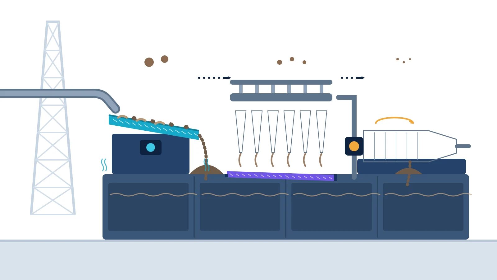
The solids control process removes unwanted drilled solids from returning drilling fluid in a planned sequence, normally beginning with shale shakers and progressing to hydrocyclones, mud cleaners and centrifuges where the fluid system requires them. Each stage targets a practical separation duty. Good performance depends on correct equipment selection, stable feed conditions, representative testing and prompt operating adjustments—not simply installing more machinery.
This guide follows the process from the flowline to the active mud system. It explains what each stage does, how the stages interact and which checks help drilling and fluids teams keep the system effective. The exact arrangement must reflect the well, fluid type, rig capacity, discharge rules and approved operating procedures.
Why solids control is a process, not a single machine
Drilling fluid returns to surface carrying formation cuttings and other solids. The fluid is needed again for well control, cuttings transport, cooling, lubrication and formation support, so the objective is selective separation: discard damaging low-gravity drilled solids while retaining a fluid with the required density, rheology and chemical properties.
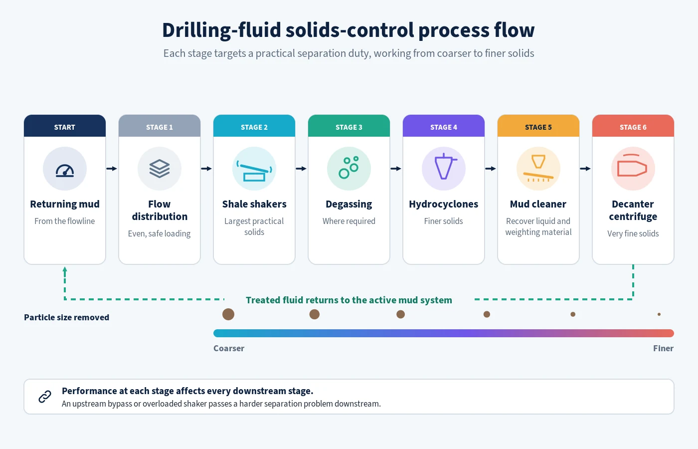
API Recommended Practice 13C provides a standard procedure for evaluating drilling-fluid processing systems and their field performance [1]. The underlying principle is that system performance should be assessed as an integrated process. An upstream bypass or overloaded shaker transfers a harder separation problem downstream, where finer solids are more difficult and often more expensive to remove.
| Process stage | Primary duty | Key operating concern |
|---|---|---|
| Flow distribution | Deliver returns evenly and safely to available capacity | Surges, blocked lines and uneven loading |
| Shale shakers | Remove the largest practical fraction first | Screen selection, deck motion, fluid coverage and bypass |
| Degassing where required | Remove entrained or free gas from the fluid | Correct placement, safe venting and stable feed |
| Hydrocyclones | Separate finer solids through pressure-driven centrifugal action | Feed pressure, cone condition and discharge pattern |
| Mud cleaner | Screen hydrocyclone underflow to recover useful liquid and weighting material | Balancing recovery against solids rejection |
| Decanter centrifuge | Manage very fine solids or split weighted-fluid fractions | Feed rate, rotational settings, differential speed and programme objective |
Step 1: Characterise the returning fluid and process duty
Start with the well section and fluid programme. Record the circulation rate, expected cuttings load, fluid type, density, rheology, particle-size distribution, weighting material and contaminants. Identify operational changes such as drilling a reactive formation, increasing the rate of penetration, sweeping the hole, circulating bottoms-up or treating a loss event.
Define what the system must achieve: maintain acceptable drilled-solids concentration, protect rheology, reduce dilution, recover valuable fluid or meet a waste-management requirement. The US Environmental Protection Agency lists drilling fluids and cuttings among the wastes generated during well drilling and completion [2]. Handling routes and discharge or disposal decisions therefore need to be built into the process rather than addressed after separation.
Step 2: Distribute flow across the shaker capacity
The flowline and distribution arrangement should deliver returns to the shale shakers without uncontrolled overflow, dead zones or unsafe exposure. Use all suitable installed capacity and balance the feed so one shaker is not overloaded while another is underused. Check possum-belly level, gates, weirs, flow dividers and bypass valves as applicable to the rig design.
Surges can cause temporary screen flooding even when average flow is within capacity. Coordinate pump-rate changes and high-solids events with the solids-control operator. A bypass may keep circulation moving, but it sends coarse cuttings into tanks and downstream equipment; treat it as an exception requiring an operational response, not normal practice.
Step 3: Remove the largest practical solids with shale shakers
Shale shakers are normally the first active separation stage. Fluid passes through the screen while oversize solids travel to the discharge. Select the finest screen that can process the full return flow reliably under current conditions. Screen designation alone is not enough: fluid viscosity, solids loading, deck angle, vibration, screen condition and conductance all affect capacity.
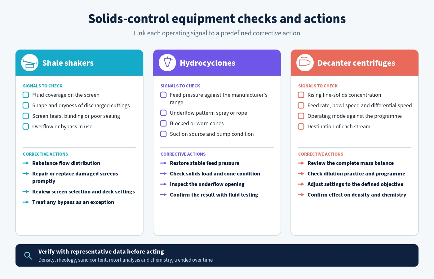
Observe fluid coverage and the dryness and shape of discharged cuttings. Inspect screens for tears, poor sealing and blinding. Repair damaged screens promptly because a small opening can contaminate the downstream system. Do not assume that drier cuttings always mean better separation; the process target is stable fluid quality with efficient liquid recovery and suitable waste handling.
Step 4: Manage entrained gas where the programme requires it
Gas in the returning fluid can reduce apparent density, disrupt pumps and change separation behaviour. Depending on the rig and well-control arrangement, gas-handling equipment may include a mud-gas separator for well-control returns and a vacuum degasser for entrained gas in the active system. These are different duties and must follow the approved well-control and process-safety design.
Confirm that venting, ignition control and hazardous-area requirements are satisfied. Monitor the fluid before and after treatment using the procedure defined for the operation. Solids-control personnel should not make changes that interfere with well-control barriers or divert gas outside an engineered route.
Step 5: Use hydrocyclones for finer separation
Hydrocyclones use feed pressure and geometry to create centrifugal separation. Larger and denser particles tend to move towards the cone wall and discharge through the underflow, while the liquid-rich overflow returns to the system. Desanders generally use larger cones than desilters; actual cut performance depends on cone design, fluid properties, particle density and operating condition.
Stable feed pressure is essential. Check the manufacturer’s operating range, suction source, pump condition, blocked cones and manifold losses. Observe the underflow pattern: a spray indicates a different loading condition from a rope-like discharge, which may signal overloading or restricted operation. Never adjust only by appearance; verify the result through fluid testing and mass-balance reasoning.
The process sequence is also recognised in technical literature: staged arrangements commonly use shale shakers, hydrocyclones and centrifuges, with each stage affecting the next [3]. Professionals responsible for these decisions can deepen their system-level understanding through EPW’s Drilling Fluids Technology and Solids Control Systems course.
Step 6: Recover useful fluid through the mud cleaner
A mud cleaner combines hydrocyclones with a fine vibrating screen. The cones concentrate solids in their underflow; the screen then separates larger unwanted material while allowing liquid and appropriately sized weighting material to return. This can be valuable in weighted systems where discarding the complete hydrocyclone underflow would waste fluid and barite.
Set the unit according to the fluid-management objective. Confirm screen integrity, cone pressure and the destination of both streams. A recovery-first setting that returns excessive drilled solids is false economy, while indiscriminate disposal can increase treatment volume and cost.
Step 7: Apply decanter centrifuges to the fine-solids problem
A decanter centrifuge separates particles under a much greater effective gravitational field than tanks or hydrocyclones. Fluid enters a rotating bowl; separated solids move towards the discharge through the differential action of the scroll. Feed rate, bowl speed, differential speed, pond depth and fluid condition influence the cut.
The operating mode depends on the programme. In an unweighted system, the aim may be to reject fine drilled solids and recover usable liquid. In a weighted system, a two-stage or selective process may be used to manage low-gravity solids while recovering barite-rich material. The fluids engineer should define where each stream goes and how the treatment affects density and chemistry.
Step 8: Verify performance with representative data
Sample at locations that answer a defined question, such as before and after an equipment stage. Apply consistent field-testing methods and record the time, well activity, flow rate and treatment state. Useful measures may include fluid density, rheology, sand content, retort analysis, chloride or other chemistry, screen use, dilution volume, discarded volume and equipment uptime.
Trend the data rather than reacting to one isolated result. Increasing low-gravity solids may reflect screen bypass, insufficient capacity, poor hydrocyclone feed, inefficient centrifuge settings or formation dispersion. Diagnose the process before adding dilution or chemical treatment. API’s drilling-fluid standards catalogue distinguishes field testing of water- and oil-based fluids from the processing-system evaluation covered by RP 13C [4].
Step 9: Control waste streams and protect people
Define containment, transfer, storage, treatment and final handling for shaker cuttings, hydrocyclone underflow, centrifuge solids and spent fluid. Characterise waste under the applicable jurisdiction and contract. Prevent incompatible mixing, uncontrolled drainage and overfilled containers. Record quantities where they support compliance and performance analysis.
Guard moving machinery, manage vibration and noise, control slips and splashes, and use suitable procedures for screen changes and maintenance. Chemical and fluid safety data should inform personal protective equipment and exposure controls. Environmental planning can be developed further through EPW’s Environmental Impact Assessment in Oil and Gas Projects course.
Common process failures and responses
- Shaker overflow: check distribution, screen condition, deck settings, fluid properties and available capacity before opening a bypass.
- Frequent screen failure: examine installation, tensioning or sealing, loading, storage and handling.
- Roping hydrocyclones: verify pressure, solids load, cone condition and underflow opening.
- Rising fine-solids concentration: review the complete mass balance, dilution practice and centrifuge programme.
- Excessive fluid loss with cuttings: optimise screens and dryers where approved without returning damaging solids.
- Good equipment readings but poor mud properties: verify sampling, calibration, chemistry and whether the chosen separation target fits the fluid.
A practical shift checklist
- Confirm current well activity, circulation rate, fluid system and treatment target.
- Inspect flow distribution and ensure required units are available.
- Check shaker screen condition, fluid coverage and discharge.
- Verify hydrocyclone feed pressure and underflow behaviour.
- Confirm centrifuge operating mode, feed and stream destinations.
- Take representative samples and trend fluid properties and solids indicators.
- Record bypasses, downtime, dilution, waste volumes and corrective action.
- Communicate material changes to drilling, fluids, HSE and waste personnel.
Build control around the complete fluid loop
The solids-control train succeeds when its stages work as one process. Remove the largest practical fraction first, protect downstream equipment from overload, define the purpose of fine-solids treatment and verify the result through representative data. Link operating limits to action so that deteriorating performance is corrected before it becomes a fluid, waste or drilling problem.
EPW’s Drilling Fluids Technology and Solids Control Systems training connects fluid properties, equipment operation and troubleshooting. Related learning includes Advanced Oil and Gas Exploration and Production Fundamentals, Oilfield Services and Equipment Management and the broader Oil, Gas and Energy training portfolio.
Sources and references
- American Petroleum Institute, Exploration and Production Standards Catalogue: RP 13C.
- US Environmental Protection Agency, Management of Oil and Gas Exploration and Production Waste.
- Irawan and colleagues, Solids Control System in Drilling Operations.
- American Petroleum Institute, drilling-fluid and well-construction standards overview.
- SLB, Solids Control and Cuttings Management.