

AI-generated illustration created to represent the article’s subject. It does not depict an actual EPW course, trainer, participant, client, event or venue.
Advanced metering infrastructure (AMI) is an integrated system of smart meters, two-way communications networks and utility data-management platforms. It measures electricity use at defined intervals, transports readings and events securely, and returns authorised commands or information to field devices. For utility engineers and grid-modernisation teams, AMI is therefore an operational architecture—not simply a collection of digital meters.
The US Department of Energy describes AMI as an integrated combination of smart meters, communications networks and data-management systems that enables two-way communication between utilities and customers. This definition appears in the Department’s smart-grid technology study. The practical value comes from connecting these layers reliably, maintaining trustworthy time-series data and integrating the result with billing, outage, customer and distribution applications.
Key takeaways
- A smart meter is one device; AMI is the end-to-end system around it.
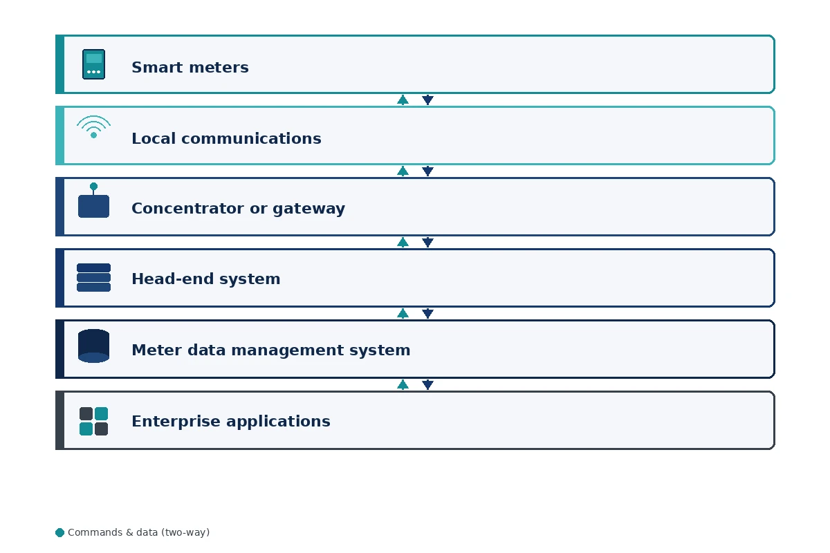
- Core layers include meters, field communications, a head-end system, meter data management and enterprise integrations.
- Data quality, interoperability, cybersecurity and operating ownership matter as much as meter accuracy.
- An AMI business case should link each use case to the data, latency, integration and control capabilities it actually requires.
What does advanced metering infrastructure mean?
AMI means the complete technical and organisational chain used to collect, validate, store and apply interval meter data while supporting authorised two-way exchanges with field devices. Depending on the implementation, the exchange may carry readings, voltage information, outage notifications, tariff data, clock updates, firmware packages and control commands.
A conventional meter may require a person to collect a cumulative reading. Automated meter reading can transmit readings in one direction. AMI normally adds sustained two-way communications, more granular data, remote device management and integration with utility applications. Those distinctions affect network design, cybersecurity, data governance and operating procedures.
AMI versus a smart meter
| Aspect | Smart meter | Advanced metering infrastructure |
|---|---|---|
| Scope | A field device at a customer or network connection point | An end-to-end system spanning devices, communications, data platforms and integrations |
| Primary function | Measure, time-stamp and store electrical quantities and events | Collect, validate, distribute and act on data across utility processes |
| Communications | Contains or connects to a communications interface | Includes the managed network, protocols, availability targets and security controls |
| Operational ownership | Metering and field-service responsibilities | Shared ownership across metering, telecoms, IT, cybersecurity, billing and grid operations |
| Value | Depends on device capability and accuracy | Depends on reliable integration and usable business processes as well as devices |
Core components of an AMI system
1. Smart meters and field devices
Smart meters measure consumption and may record demand, voltage, power-quality indicators, tamper events and outage/restoration messages. The exact functions depend on the meter specification, regulatory rules and use case. Device identity, clock accuracy, local storage, event configuration and firmware governance all influence the quality of downstream information.
2. Neighbourhood and wide-area communications
The field network transports data between meters and the utility. Common architectures use radio-frequency mesh, cellular services, power-line communications or combinations of technologies. Selection should follow coverage, latency, throughput, resilience, spectrum, lifecycle cost and security requirements—not a preference for one communications label.
3. Data concentrators or gateways
Some topologies aggregate traffic from groups of meters before forwarding it to the utility. A concentrator can manage local communications, buffer data and reduce the number of direct wide-area connections. It also becomes an asset that needs configuration control, monitoring and a recovery plan.
4. Head-end system
The head-end communicates with meters or field gateways. It schedules collections, receives events, manages device sessions and passes data onwards. The head-end is generally device- and protocol-facing, so its availability and interfaces are central to field operations.
5. Meter data management system
The meter data management system receives readings from one or more head-end systems, applies validation, estimation and editing rules, maintains meter and channel relationships, and prepares data for authorised users. It should preserve quality flags and audit history so that an estimated value is not mistaken for a directly observed reading.
6. Enterprise and operational systems
AMI becomes useful when governed interfaces connect it to billing, customer information, outage management, distribution management, analytics, demand-response and planning systems. NIST’s research on smart-grid resilience benefits notes the value of integrating AMI with billing, customer, outage and distribution-management applications.
How does AMI data flow from the meter to the utility?
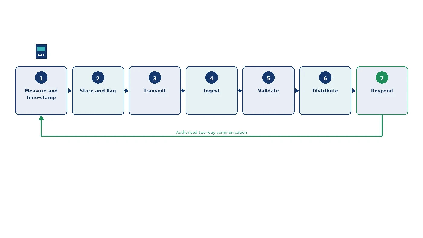
The following seven-stage model explains a typical collection cycle. Real systems may combine stages or use event-driven messages, but separating the stages helps teams assign controls and diagnose failures.
- Measure and time-stamp. The meter samples electrical quantities, calculates configured values and associates them with a reliable clock.
- Store and flag. Interval readings and events are retained locally with status information, such as missing intervals, outages or clock changes.
- Transmit. The meter sends data through the field network directly or through a concentrator. The network applies addressing, authentication and delivery controls appropriate to the design.
- Ingest. The head-end receives the payload, associates it with the correct device and records communications or collection exceptions.
- Validate. The meter data management system checks completeness, timing, plausible ranges and relationships with adjacent intervals. Approved rules may estimate missing values while retaining an audit trail.
- Distribute. Authorised systems receive fit-for-purpose datasets. Billing may need validated settlement intervals, while outage analytics may need events with lower latency.
- Respond. An authorised workflow may return a tariff update, configuration change, firmware package or control command. The system should verify permission, delivery and device response.
This model exposes an important design principle: data latency should follow the use case. Monthly billing and near-real-time outage awareness do not require the same collection schedule, communications priority or integration pattern. Specifying “fast data” without an operational decision and owner can create cost without value.
What can AMI support?
AMI can support several applications, but each one needs specific data and integration. It may enable remote meter reading, billing based on interval data, outage and restoration notifications, voltage analysis, loss investigation, customer usage information and selected demand-response programmes. The US Department of Energy’s analysis of 63 Smart Grid Investment Grant projects examined operational effects including lower meter-operation costs and support for customer service and distribution functions.
Teams should avoid claiming every possible benefit for every deployment. For example, outage detection depends on event delivery, connectivity during a power interruption, correlation logic and integration with outage-management processes. Better voltage insight depends on meter capability, sampling design, location coverage and the way analysts interpret the data.
Where interval data is intended to support flexible demand, the operating model should be aligned with demand-side management and energy-efficiency practices. Where AMI events inform real-time network supervision, integration boundaries with SCADA and power-system automation must be explicit.
Architecture, interoperability and security risks
AMI expands the number of connected field assets, interfaces and identities that a utility must manage. NIST maintains a dedicated smart-grid cybersecurity programme and has developed guidance and testing work related to AMI smart-meter upgradeability. Security therefore belongs in requirements, architecture, procurement, testing and operations rather than being added after deployment.
Important controls include unique device identity, authenticated communications, encryption where appropriate, key management, role-based access, logging, secure configuration, signed firmware, vulnerability handling, network segmentation, backup and tested recovery. The US Department of Energy’s AMI System Security Requirements provides a recognised requirements reference for utilities and vendors.
Interoperability is equally important. A technically successful meter installation can still produce weak results when identifiers differ between systems, data semantics are inconsistent or vendor interfaces cannot support required workflows. Interface contracts should define ownership, formats, timing, quality flags, error handling, versioning and test evidence.
AMI architecture decision checklist
| Decision area | Question to resolve | Evidence required |
|---|---|---|
| Use cases | Which operational or customer decision will the data support? | Named owner, process map and measurable outcome |
| Data | Which quantities, intervals, events and quality flags are required? | Data specification and retention rules |
| Communications | What coverage, latency, availability and recovery targets apply? | Survey, capacity model and resilience test |
| Integration | Which system is authoritative for each identifier and status? | Interface contract and end-to-end test cases |
| Security | How are devices, users, keys, firmware and logs governed? | Threat model, control design and incident procedures |
| Operations | Who owns failures that cross meter, network and application boundaries? | Responsibility matrix and support workflow |
| Lifecycle | How will devices and software be patched, replaced and retired? | Upgrade, compatibility and asset-disposal plans |
The checklist is an EPW planning aid rather than a technical standard. Utilities should adapt it to their jurisdiction, regulatory obligations, network model, procurement rules and approved security framework.
Building professional capability for AMI programmes
AMI decisions cross electrical engineering, communications, data, cybersecurity and programme governance. EPW’s five-day Smart Grids and Advanced Metering Infrastructure course covers smart-grid architecture, AMI components, communications options, interoperability, meter-data applications, cybersecurity and implementation planning. Prospective participants should compare the published outline with their role and current project phase.
Professionals can also review the wider Electrical Power and Energy Engineering training portfolio when their development need extends into distribution automation, grid integration, protection or power-system analysis.
Conclusion
Advanced metering infrastructure is the operational chain that turns field measurements into governed utility information and, where authorised, carries instructions back to devices. A sound design starts with use cases, then aligns meters, communications, platforms, interfaces, security and ownership. The seven-stage data-flow model and decision checklist give project teams a practical basis for testing whether the architecture is complete.
Ready to develop AMI architecture and implementation skills? Explore EPW’s Smart Grids and Advanced Metering Infrastructure course, review available dates and locations, or request tailored in-house training.
Sources and References
- US Department of Energy. Innovation Pathway Study: Smart Grid Technologies. December 2016. Source.
- National Institute of Standards and Technology. NIST Framework and Roadmap for Smart Grid Interoperability Standards, Release 3.0. September 2014. Source.
- National Institute of Standards and Technology. Quantifying Operational Resilience Benefits of the Smart Grid. 2021. Source.
- US Department of Energy. Operations and Maintenance Savings from Advanced Metering Infrastructure. December 2012. Source.
- National Institute of Standards and Technology. Cybersecurity for Smart Grid Systems. Accessed 9 September 2026. Source.
- US Department of Energy. AMI System Security Requirements, Version 1.01. 17 December 2008. Source.
- EPW Training. Smart Grids and Advanced Metering Infrastructure Course. Accessed 9 September 2026. Source.