

AI-generated illustration created to represent the article’s subject. It does not depict an actual EPW course, trainer, participant, client, event or venue.
EV charging hosting capacity is the additional charging load a distribution network can accommodate under defined operating scenarios without unacceptable thermal, voltage, power-quality, protection or reliability impacts. It is not one permanent megawatt limit. A useful framework must represent where charging occurs, when vehicles connect, how much energy they need and whether charging can be managed.
This article gives distribution planners, connection engineers, fleet electrification teams and charging developers a repeatable framework for analysing electric vehicle (EV) charging load. The result should support decisions about site connection, managed charging, monitoring and network reinforcement—not replace a detailed interconnection or connection study.
Key takeaways
- Model energy and power: a site may need substantial daily energy but have flexibility in its coincident peak.
- Location matters: identical charging sites can have different impacts on different transformers, feeder sections and substations.
- Use scenarios rather than one forecast: adoption, arrival time, dwell time, charger rating and diversity are uncertain.
- Test operational criteria together: thermal loading, voltage, power quality, protection and contingency performance interact.
- Managed charging can increase usable capacity: its communications, fail-safe behaviour and customer constraints must be modelled honestly.
What EV charging hosting capacity means
For this framework, hosting capacity is a scenario-dependent planning result: the maximum additional EV charging demand that can be connected at a defined location, under specified load, network and control assumptions, before a chosen technical criterion is violated or an upgrade becomes necessary. It can be expressed as connected kilowatts, simultaneous kilowatts, charger count, vehicle count or energy served within an operating window.
The definition must state its boundary. A transformer-only screen is not feeder hosting capacity. A feeder result may exclude upstream substation capacity. A static map may not reflect a queued project, a seasonal topology change or a new control scheme. The U.S. Department of Energy’s Atlas of Electric Distribution System Hosting Capacity Maps shows that utilities publish maps for different applications, including EV, load and distributed generation. Their labels and assumptions should be read before comparing values.
Purpose and decision scope
An EV charging hosting-capacity study should answer a defined decision, such as:
- Where can near-term public, workplace or fleet charging connect with minimal reinforcement?
- How many chargers can a site operate under an agreed power ceiling?
- Which transformer or feeder constraint will appear first as adoption grows?
- Could time control, dynamic load management or behind-the-meter storage defer an upgrade?
- What measurement and communications are required to rely on managed charging?
- When should a screening result escalate to a detailed connection study?
The National Renewable Energy Laboratory EVI-X modelling suite separates network planning, site design and financial analysis. Its EVI-DiST capability provides high-fidelity distribution-grid insight for utilities and assesses increasing EV load together with practical control strategies. This illustrates why transport demand and electrical-network models must exchange consistent location and time-series data.
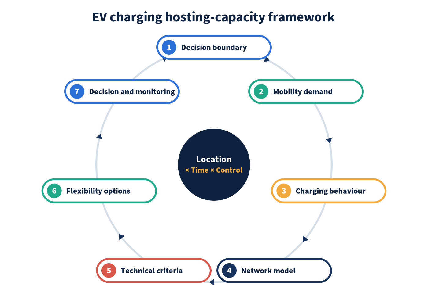
The EPW seven-part hosting-capacity framework
| Component | Core question | Required evidence | Output |
|---|---|---|---|
| 1. Decision boundary | What decision, geography, voltage level and planning horizon are in scope? | Planning brief, connection rules, asset ownership and study criteria | Approved scope and escalation rules |
| 2. Mobility demand | Which vehicles need energy, where and by when? | Fleet duty cycles, travel surveys, adoption scenarios, arrival and departure times | Vehicle-energy requirements by place and time |
| 3. Charging behaviour | How does required energy become electrical demand? | Charger ratings, efficiency, dwell time, access rules, utilisation and charging logic | Diversified time-series charging profiles |
| 4. Network model | Which assets and operating states determine capacity? | Feeder topology, impedances, transformer ratings, load profiles, voltage controls and protection data | Validated base-case power-flow model |
| 5. Technical criteria | What constitutes an unacceptable result? | Utility planning standards and applicable statutory, grid-code and equipment limits | Explicit pass/fail thresholds |
| 6. Flexibility options | Which controls or upgrades may release capacity? | Charging deadlines, communications capability, fail-safe rules, tariffs, storage and reinforcement options | Credible mitigated scenarios |
| 7. Decision and monitoring | How will the result govern action and remain current? | Sensitivity results, uncertainty range, measurement plan and review triggers | Connection envelope, action plan and refresh cycle |
How to apply the framework
1. Define the study question and boundary
State the decision before building the model. Record the study area, voltage levels, asset boundaries, base year, forecast years, charging segments and whether the result is a screening estimate or a formal connection assessment. Define the minimum information that will trigger a detailed study.
2. Convert transport activity into energy requirements
Estimate vehicle kilometres, energy consumption, state of charge on arrival, arrival time, departure deadline and required reserve. Use separate segments for home, workplace, depot, destination and corridor charging because their coincidence and flexibility differ. NREL’s demand-side grid toolkit demonstrates the value of spatially and temporally resolved load data for power-system analysis rather than simply scaling historical demand.
3. Build diversified charging profiles
Do not multiply charger nameplate power by charger count and call that the forecast. Create time-series profiles using connection probability, energy need, dwell time, charger availability, sharing rules and control logic. Include an unmanaged case, credible managed cases and a communication-failure case.
The U.S. Department of Energy defines managed EV charging as strategic control of when and how vehicles charge without compromising operational needs. Controls may enforce a site power ceiling, avoid peak periods or respond dynamically to facility load. The analysis must preserve departure-energy requirements; otherwise it overstates flexibility.
4. Validate the distribution-network base case
Reconcile the feeder model with switching state, supervisory control and data acquisition measurements, advanced metering data and asset records. Check phase allocation, regulator and capacitor controls, transformer taps, embedded generation, normal and abnormal configurations, and upstream constraints. Poor base data can produce a precise but unusable hosting-capacity number.
5. Define technical pass/fail criteria
Use the network owner’s applicable criteria and document them. Typical tests include conductor, cable and transformer loading; steady-state voltage; voltage unbalance; voltage-control operations; harmonic or flicker screening; fault level; protection sensitivity and coordination; restoration configuration; and upstream substation or transmission limits.
6. Run locational, temporal and control scenarios
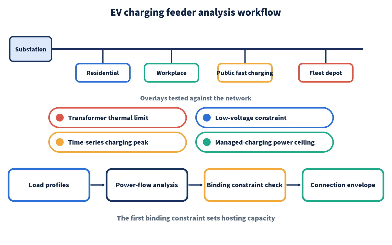
Add EV load incrementally at candidate nodes or groups of nodes. Run representative hours or full time series across seasonal minimum and maximum load, high distributed-generation output, relevant contingencies and forecast years. Record the first violated criterion and the amount, location and timing of the breach.
7. Test mitigation and issue a decision envelope
Evaluate phase balancing, charging power limits, staggered schedules, dynamic load management, voltage-control changes, transformer replacement, feeder reinforcement, new circuits or substations, and behind-the-meter storage. Compare cost, lead time, resilience and operational dependencies. The final output should state a connection envelope and conditions—not only a colour on a map.
Completed example: a fleet depot connection
Consider a hypothetical depot proposing 40 chargers rated at 22 kW each. The nameplate total is 880 kW, but the vehicles return in two waves and require different energy before morning departure. The depot sits behind a 1 MVA transformer that also supplies a building with a variable evening load. This is an illustrative method, not a claimed real project.
The planning team models four cases:
- Unmanaged nameplate case: all available vehicles begin charging on connection.
- Diversified unmanaged case: arrival times, state of charge and charger sharing vary.
- Managed 600 kW site ceiling: charging is scheduled to meet each departure deadline while limiting total site demand.
- Control-failure case: communications are unavailable and chargers revert to a documented safe limit.
The unmanaged case produces an evening transformer overload. Diversity reduces the duration but not the worst seasonal breach. The managed case passes the transformer and voltage criteria while meeting the modelled vehicle-energy requirements. The failure case passes only if a local fallback limit is configured. The decision is therefore conditional: connect within a 600 kW import envelope, implement verified local fallback, provide operational telemetry and review the limit if vehicle schedules or building load materially change.
This example shows why a hosting-capacity result should include operating conditions and monitoring. A bare statement that the depot has “880 kW of capacity” or “no capacity” would hide the value of controlled diversity and the dependency on reliable fallback behaviour.
How to interpret the results
| Result pattern | Interpretation | Planning response |
|---|---|---|
| Thermal limit binds for only a few intervals | Flexible charging may defer reinforcement | Test a power ceiling and departure-energy feasibility |
| Voltage limit binds at a remote node | Location and phase connection are material | Compare alternative nodes, phase balancing and voltage-control options |
| Substation limit binds across several feeders | A local feeder solution may shift rather than solve the problem | Coordinate upstream planning and portfolio timing |
| Protection or power-quality criteria bind | Power-flow headroom alone is not sufficient | Perform detailed equipment, fault and waveform studies |
| Managed case passes but failure case fails | Hosting capacity depends on communications and control integrity | Specify fallback limits, monitoring, alarms and contractual responsibilities |
| Result changes sharply across scenarios | Uncertainty is decision-relevant | Publish a range, define triggers and use staged investment |
The Department of Energy’s EVGrid Assist resources emphasise proactive planning that combines infrastructure upgrades, load-management approaches and consumer participation. They also describe tools such as GridLAB-D and Caldera for detailed grid and charging-load analysis. Tool selection should follow the question, data quality and required assurance level.
Advantages, limitations and related approaches
Advantages
- Connects charging deployment to network investment timing.
- Makes the value and conditions of managed charging visible.
- Supports consistent screening across many candidate sites.
- Identifies the binding asset, location, interval and technical criterion.
- Creates an auditable bridge between forecasts, engineering studies and connection decisions.
Limitations
- Results are only as reliable as feeder, asset and charging-behaviour data.
- Fast-changing queues, switching states and customer adoption can make static maps stale.
- A screen may omit harmonics, protection, resilience or upstream constraints.
- Managed-charging assumptions may fail if communications, incentives or contractual controls are weak.
- One maximum value can conceal uncertainty and unequal capacity across phases or nodes.
Hosting-capacity analysis complements, but does not replace, integrated distribution planning, load forecasting, connection studies, non-wires alternatives assessment and site-level electrical design. Public maps are useful for early siting. A developer should still engage the serving utility: the U.S. Alternative Fuels Data Center notes that utilities can analyse power availability and capacity and may offer managed charging to mitigate grid impacts in its EV infrastructure planning resources.
Practical quality checklist
- Is the decision, geography, voltage level and time horizon explicit?
- Are charger power and vehicle energy needs modelled separately?
- Are unmanaged, managed and control-failure cases included?
- Does the base model reflect current topology, controls and queued connections?
- Are thermal, voltage, power-quality, protection and upstream limits tested?
- Does every mitigated result state its communications and operational dependencies?
- Is the output a range or envelope with assumptions, rather than a misleading permanent number?
- Are monitoring metrics and model-refresh triggers assigned to an owner?
Develop practical EV grid-integration capability
Sound hosting-capacity work requires more than running a power-flow case. Practitioners must connect transport demand, charging behaviour, distribution modelling, technical criteria, managed charging and investment decisions. EPW’s Electric Vehicle Charging Infrastructure and Grid Impact course develops these connected planning and engineering skills.
Explore this course and related programmes in the Electrical Power and Energy Engineering training category to identify the most relevant route for your responsibilities.
Conclusion
An EV charging hosting-capacity framework should produce a transparent, conditional connection decision. The seven-part method starts with the decision boundary, converts mobility demand into time-series electrical load, tests a validated network against multiple technical criteria, evaluates credible flexibility and reinforcement, and ends with a monitored connection envelope. That is more useful than a single megawatt figure detached from location, time and control.
Sources and References
- National Renewable Energy Laboratory. EVI-X Modeling Suite of Electric Vehicle Charging Infrastructure Analysis Tools. Accessed 14 September 2026. Official resource.
- U.S. Department of Energy. EVGrid Assist: Resources, Reports, and Tools. Accessed 14 September 2026. Official resource.
- U.S. Department of Energy. U.S. Atlas of Electric Distribution System Hosting Capacity Maps. Accessed 14 September 2026. Official atlas.
- U.S. Department of Energy, Federal Energy Management Program. Managed EV Charging for Federal Fleets. Accessed 14 September 2026. Official guidance.
- National Renewable Energy Laboratory. dsgrid: Demand-Side Grid Toolkit. Accessed 14 September 2026. Official toolkit page.
- U.S. Department of Energy, Alternative Fuels Data Center. Procurement and Installation for Electric Vehicle Charging Infrastructure. Accessed 14 September 2026. Official planning resource.