LCC-HVDC vs VSC-HVDC is a comparison between two high-voltage direct-current transmission technologies; neither is universally better. Line-commutated converter (LCC) systems remain a strong option for very high-power point-to-point transfer between sufficiently strong alternating-current networks. Voltage-source converter (VSC) systems offer independent active and reactive control, compact stations and connection to weak or passive networks, making them especially relevant to offshore wind, constrained sites and multi-terminal development.
A defensible selection must compare the complete scheme—not only converter losses or maximum rating. Transmission owners and project engineers must assess power scale, AC-system strength, overhead-line or cable route, control objectives, fault behaviour, land, harmonics, reliability, expandability and whole-life economics.
Key takeaways
- LCC-HVDC uses line-commutated thyristor valves and depends on a suitably strong AC voltage for commutation.
- VSC-HVDC uses self-commutated semiconductor valves, now commonly in a modular multilevel converter (MMC), and can regulate active and reactive power independently within its capability.
- LCC is established for very large bulk-power, long-distance links; VSC is highly adaptable to cables, offshore networks, weak grids and multi-terminal arrangements.
- LCC stations usually require more reactive compensation and filtering; VSC stations are generally more compact but have different valve, DC-fault and control challenges.
- The decision should follow common assumptions and validated load-flow, dynamic, harmonic, insulation, electromagnetic-transient, reliability and economic studies.
How LCC-HVDC and VSC-HVDC convert power
LCC-HVDC
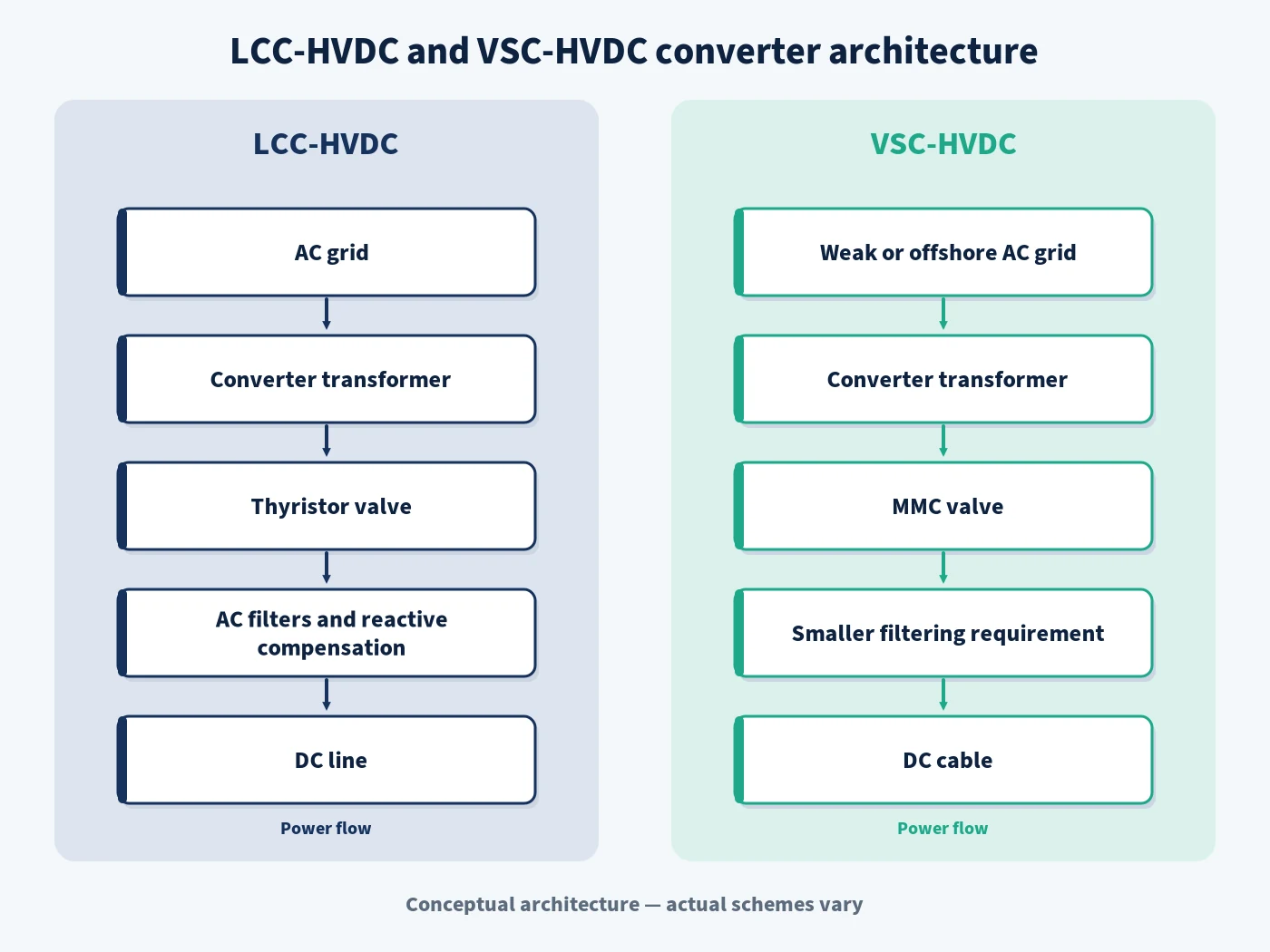
An LCC station uses thyristor valves whose turn-off depends on the alternating-current system. Converter transformers adapt voltage and phase, while smoothing reactors, AC and DC filters, switchgear, controls and protection complete the scheme. Because the converter consumes reactive power, shunt capacitors, filters or dynamic compensation are normally part of station design.
IEC 60146-1-1:2024 covers general semiconductor-converter requirements and requirements applicable to line-commutated converters. Hitachi Energy’s LCC-HVDC technology overview describes the technology as primarily serving remote generation, long-distance transfer and AC-system interconnection, with many installations in the 1,000–12,000 MW range. Those supplier figures indicate market experience, not a universal project limit.
VSC-HVDC
A VSC station uses self-commutated semiconductor valves. Modern schemes generally use MMC submodules to synthesise an AC waveform with relatively low harmonic content. The converter can control active power and reactive power independently within voltage, current, energy and thermal limits, and it can connect to an AC system without relying on that system for valve commutation.
VSC capability makes weak-network, islanded and offshore connections feasible, subject to control design and auxiliary-power arrangements. CIGRE’s HVDC circuit-breaker technical summary identifies VSC as an enabler for multi-terminal and meshed DC systems. It does not mean every VSC link is automatically multi-terminal or black-start capable; those functions must be specified and validated.
LCC-HVDC vs VSC-HVDC comparison table
| Criterion | LCC-HVDC | VSC-HVDC | Selection meaning |
|---|---|---|---|
| Valve principle | Line-commutated thyristors | Self-commutated VSC valves, commonly MMC | Changes commutation dependency, control, losses, harmonics and protection |
| AC-system strength | Requires adequate AC voltage and short-circuit strength for reliable commutation | Can connect to weak or passive AC networks | Weak receiving networks often favour VSC or require substantial LCC support |
| Power and route fit | Well established for very high-power point-to-point overhead and cable links | Strong fit for cable systems, offshore wind, constrained corridors and expanding DC networks | Use current supplier guarantees and project-specific economics |
| Reactive power | Consumes reactive power; compensation is integral to the station | Controls reactive power within its capability independently of active-power order | AC network and station equipment differ materially |
| Power reversal | Conventionally reverses DC voltage polarity while current direction remains | Typically reverses DC current while voltage polarity remains | Cable insulation, multi-terminal design and controls must match the chosen philosophy |
| AC harmonics | Requires substantial AC filters and reactive plant | MMC waveform usually reduces AC-filter requirements | Both still require harmonic and resonance studies |
| Footprint | Generally larger because of filters and compensation | Generally more compact | Offshore platforms and urban sites may place high value on space and weight |
| Fault behaviour | Susceptible to commutation failure during severe AC disturbances; controls manage recovery | No line-commutation failure, but converter current limits, blocking and DC-fault response are decisive | Compare credible AC and DC fault sequences in EMT studies |
| Multi-terminal development | Possible but control and polarity conventions complicate expansion | Well suited to multi-terminal concepts and DC-grid development | Expansion rights, interoperability and DC protection must be defined early |
| Economic tendency | Often compelling at the highest bulk-power duties | Can offset converter cost through cables, compact sites and system services | Use total scheme net present cost and sensitivity analysis |
Grid strength, commutation and controllability
LCC depends on the AC voltage waveform to transfer current from one thyristor valve to the next. A low short-circuit level, adverse impedance, nearby faults or voltage distortion can reduce commutation margin and cause commutation failure at an inverter. The engineering response may include stronger AC connections, synchronous condensers, SVC or STATCOM support, control tuning and appropriate operating limits.
VSC does not depend on line commutation, so it can energise or support a weak AC network when the control and station auxiliaries are designed for that duty. It can regulate AC voltage or reactive power while controlling DC voltage or active power. However, low system strength can still create converter-control interactions; “works with weak grids” is not permission to skip impedance scans, electromagnetic-transient (EMT) studies or model validation.
Siemens Energy’s HVDC transformer overview distinguishes LCC’s bulk long-distance applications from VSC’s offshore, multi-terminal and dynamic grid-stabilisation applications. CIGRE similarly states that both technologies can integrate renewable energy while describing LCC as the continuing workhorse for high-power point-to-point links in its DC systems and power-electronics review.
Station equipment, losses and footprint
LCC converter stations normally include larger AC filter banks and reactive-power compensation. The filter banks also contribute reactive power, making switching sequence, minimum power, temporary overvoltage and resonance part of the operating design. VSC MMC stations can generate a waveform that reduces filtering needs and generally use less land, although the valve hall, converter reactors, transformers, cooling, DC yard and auxiliary systems remain substantial assets.
Loss comparisons must use the same scope and operating points. A single peak-load efficiency number can hide auxiliary power, transformer losses, filters, reactive plant, cable or line losses, minimum-load operation and availability. The economic model should calculate annual energy losses across realistic transfer-duration curves and apply consistent energy values, discount rates, asset lives and outage costs.
Converter transformers are specialised in both technologies. They provide voltage adaptation and isolation and withstand combined stresses, harmonic loading and dynamic duty. VSC and LCC designs impose different valve-side waveforms, insulation arrangements and operational requirements; a generic AC transformer specification is inadequate.
Where each HVDC technology usually fits
Applications that often favour LCC-HVDC
- Very high-power transfer over a long overhead-line corridor.
- Point-to-point interconnection between strong AC systems.
- Remote hydro or thermal generation evacuation at very large scale.
- Projects where established ultra-high-voltage ratings and low bulk-transfer cost dominate.
These are tendencies, not automatic rules. Cable technology, environmental permissions, receiving-grid strength, converter-site land and operational services may change the outcome.
Applications that often favour VSC-HVDC
- Offshore wind connections and long submarine or underground cable systems.
- Supply to weak, isolated or passive AC networks.
- Back-to-back or point-to-point links requiring independent dynamic voltage support.
- Multi-terminal schemes or staged development towards a DC grid.
- Space- or weight-constrained converter sites.
- Restoration or grid-forming functions when explicitly engineered and tested.
Hitachi Energy’s VSC-HVDC overview emphasises cable transmission, compact converter stations and power-quality support. CIGRE’s guide for EMT studies involving VSC converters also makes clear that converter controls and protection shape dynamic performance throughout a VSC project’s lifecycle.
Hybrid LCC/VSC schemes
A hybrid scheme can use an LCC terminal where very high-power conversion and a strong AC system favour it, while using a VSC terminal where the receiving network, space or control requirement demands self-commutation. This is not a compromise that eliminates engineering difficulty: DC voltage polarity, power reversal, fault response, controls, protection and station interfaces must be coordinated across the complete link.
CIGRE Technical Brochure 950, summarised in February 2025, addresses hybrid LCC/VSC definitions, configurations, equipment, controls, applications and implementation issues. A hybrid option should therefore be retained during feasibility when terminal conditions are materially different, then compared with homogeneous alternatives on common technical and commercial assumptions.
EPW PATH selection framework
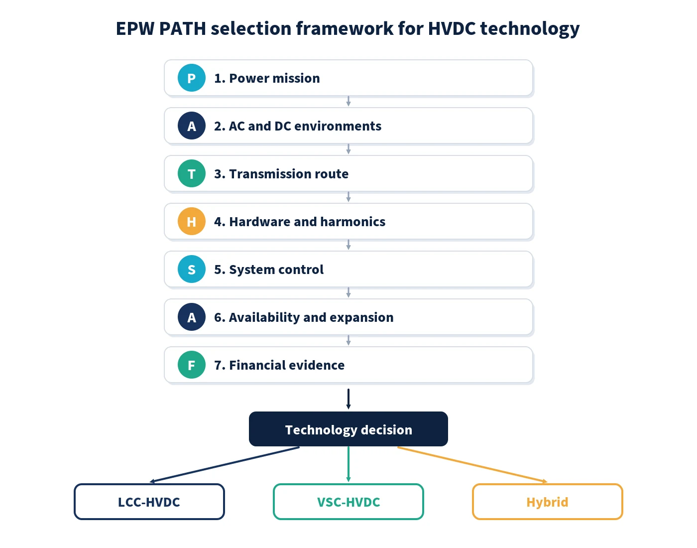
- P — Power mission: define transfer rating, direction, overload, ramp rate, minimum power, availability and required ancillary services.
- A — AC and DC environments: assess short-circuit strength, inertia, impedance, fault levels, resonances, receiving-network energisation and credible DC faults.
- T — Transmission route: compare overhead line, land cable, submarine cable or mixed route; include length, right-of-way, thermal limits, repair strategy and environmental constraints.
- H — Hardware and harmonics: size converters, transformers, filters, compensation, smoothing or converter reactors, switchgear, cooling and station auxiliaries.
- S — System control: allocate DC-voltage, active-power, reactive-power, AC-voltage, frequency and restoration roles; define limits and interactions.
- A — Availability and expansion: evaluate pole configuration, redundancy, maintainability, spare strategy, multi-terminal readiness and interoperability obligations.
- F — Financial evidence: compare capital cost, losses, land, platform, line or cable, maintenance, outages and staged investment as net present cost with sensitivities.
Worked selection scenarios
Scenario A: remote bulk generation to a strong receiving grid. A very high rating, long overhead route, strong terminal networks and limited need for independent reactive control would place LCC on the shortlist. The study must still price filters, compensation, commutation-risk mitigation, land and operational constraints.
Scenario B: offshore wind to a coastal transmission system. A submarine cable, offshore platform limits, a weak offshore AC network and the need to control offshore voltage would generally favour VSC. The design must test offshore energisation, converter interaction, DC cable faults, auxiliary supply and coordinated onshore voltage control.
Scenario C: asymmetric terminal conditions. A strong sending system with extreme bulk power and a weak receiving system may justify comparing LCC, VSC and hybrid LCC/VSC schemes. The result depends on ratings available during procurement, DC-fault philosophy, polarity constraints and the value assigned to dynamic services.
These are hypothetical decision examples, not claims about completed projects. Their purpose is to show how criteria combine; final choice requires project data and supplier guarantees.
Project studies required before technology selection
- AC and DC load flow, contingencies, transfer capability and reactive-power balance.
- Short-circuit strength and credible network-evolution scenarios at every terminal.
- RMS dynamic studies for power control, voltage, frequency and electromechanical stability.
- EMT studies for commutation failure, converter limits, blocking, fault recovery, energisation and control interaction.
- Harmonic impedance scans, filter design, resonance and power-quality compliance.
- DC and AC protection studies, fault clearing, recovery and communication failure.
- Insulation coordination, temporary overvoltage, switching surge and equipment-duty studies.
- Availability, reliability, maintainability, spares, repair logistics and obsolescence assessment.
- Common-scope cost and loss evaluation with sensitivity to energy prices, utilisation, schedule and expansion.
Model governance is part of the evidence. The owner should define required RMS and EMT model stages, parameter disclosure, version control, acceptance tests, factory real-time simulation, site validation and the handover of maintainable operational models.
Build HVDC selection and integration skills
EPW’s HVDC Transmission Systems Engineering course develops the practical basis for converter selection, station equipment, cables and lines, controls, protection, modelling and project studies. Engineers can extend this learning through the Electromagnetic Transient Analysis Using EMT Software course, the Transmission Line Design and Grid Integration course and EPW’s wider Electrical Power and Energy Engineering course category.
The selection rule is simple even when the studies are complex: choose LCC, VSC or a hybrid only after the technology has demonstrated compliance with the transfer mission, terminal networks, route, fault philosophy and lifecycle case under the same assumptions. To apply the framework to real project decisions, review available course dates and locations or request tailored in-house HVDC training through the exact EPW course page.
Sources and references
- International Electrotechnical Commission. IEC 60146-1-1:2024 — Semiconductor converters: general requirements and line-commutated converters. 19 March 2024.
- CIGRE. DC and Power Electronics — Key Enablers of Flexible, Reliable and Economic Future Networks. 12 March 2021.
- CIGRE. Guide for Electromagnetic Transient Studies Involving VSC Converters. ELECTRA No. 316, June 2021.
- CIGRE. Hybrid LCC/VSC HVDC Systems. Technical Brochure 950 summary, February 2025.
- Hitachi Energy. HVDC Classic (LCC). Technical overview, accessed 8 September 2026.
- Hitachi Energy. HVDC Light (VSC). Technical overview, accessed 8 September 2026.
- Siemens Energy. High-Voltage Direct-Current Converter Transformers. Technical overview, accessed 8 September 2026.