
Smart inverter commissioning is the controlled process of proving that an installed inverter is safe, correctly configured, interoperable with required systems and able to perform the grid-support functions specified for the project. It begins with approved requirements and equipment evidence, continues through settings and functional tests, and ends with a traceable baseline for operation and future change.
This eight-step process is designed for commissioning engineers, distribution planners, owners’ engineers, protection specialists and asset managers. It is a governance framework, not a substitute for the applicable grid code, interconnection agreement, manufacturer instructions, approved protection study or site safety procedure.
Key takeaways
- Commission against a controlled requirements matrix, not a generic inverter checklist.
- Separate product certification evidence from installation-specific commissioning evidence.
- Verify settings, time synchronisation, communications, grid-support functions and fail-safe behaviour.
- Test at the correct reference point and preserve raw evidence, not only a signed summary.
- Freeze the accepted baseline and apply formal change control to firmware, settings and communication mappings.
1. Freeze the governing requirements
Create a commissioning requirements matrix before energisation. Each row should identify the obligation, source clause, responsible party, verification method, acceptance criterion, evidence record and approver. Sources may include the local grid code, interconnection agreement, utility settings schedule, manufacturer instructions, protection study, cybersecurity rules and project specifications.
Do not assume that a capable function must be enabled or that a factory default is acceptable. IEEE 1547-2018 establishes interconnection and interoperability requirements for distributed energy resources in its scope, while jurisdictional authorities determine adoption and project-specific implementation. IEEE 1547-2018 standard record
| Requirement class | Typical controlled item | Commissioning evidence |
|---|---|---|
| Electrical | Voltage, frequency, phase rotation, grounding and isolation | Test sheet, calibrated-instrument record and signed inspection |
| Protection | Trip thresholds, clearing times, anti-islanding and reconnection | Settings file, injection or functional-test record and event log |
| Grid support | Volt-var, watt-var, volt-watt, frequency-watt and power factor | Approved curves, command response and measured output |
| Interoperability | Readable data, writable parameters, protocol mapping and access | Point-to-point test, timestamps, permissions and command audit trail |
| Handover | Firmware, configuration, drawings, passwords and responsibilities | As-left baseline and accepted commissioning dossier |
2. Verify equipment and certification evidence
Confirm the installed manufacturer, model, ratings, serial numbers, firmware and communication options against the approved equipment schedule. Check that product certificates and test reports apply to the exact hardware and firmware combination. Record substitutions and deviations; do not treat a similar model as equivalent without technical acceptance.
Product conformance testing and site commissioning answer different questions. IEEE 1547.1-2020 specifies type, production, commissioning and periodic tests used to verify conformance with IEEE 1547 requirements. A certificate can support product capability, but the project still needs evidence that the installed device, wiring, settings and interfaces are correct. IEEE 1547.1-2020 standard record
3. Complete pre-energisation checks
Use the approved inspection and test plan. Verify mechanical installation, conductor termination, torque records, insulation checks where applicable, grounding and bonding, current-transformer and voltage-transformer polarity, auxiliary supplies, cooling, emergency stops, isolation devices and protection wiring. Confirm that labels, boundaries and access controls match the operating procedure.
The responsible safety authority must determine the energisation sequence and precautions. Commissioning personnel should not bypass interlocks or protective functions merely to accelerate testing. Any temporary test configuration needs documented approval, a defined removal step and independent confirmation that the normal arrangement has been restored.
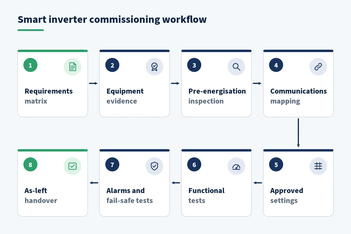
4. Establish communications and control ownership
Define which system is allowed to read data, change settings, issue active-power or reactive-power commands and update firmware. Test the complete path among the inverter, plant controller, supervisory control and data acquisition system, utility interface and time source. Point names, units, signs, scaling, quality flags and timestamps must be consistent.
IEEE 1547.1-2020 includes interoperability testing associated with communication, control and telemetry. IEEE’s standards material identifies IEEE 2030.5, IEEE 1815/DNP3 and SunSpec Modbus among the relevant communication approaches for distributed energy resource interfaces. IEEE Standards Coordinating Committee 21 summary of IEEE 1547.1-2020
Test both successful and unsuccessful transactions. Confirm how the system behaves when communications are lost, credentials expire, a value is out of range or two controllers attempt to write the same setting. The intended source of authority must be explicit.
5. Load and independently verify approved settings
Import or enter settings only from the authorised schedule, then perform an independent comparison between the approved file and the values read back from the device. A screen capture alone is insufficient when a machine-readable export, checksum or structured comparison is available.
- Nominal voltage and frequency
- Voltage and frequency trip and ride-through parameters
- Reconnection conditions and intentional delay
- Reactive-power capability and priority logic
- Volt-var, watt-var and constant power-factor settings
- Volt-watt and frequency-watt settings
- Ramp rates, soft start and active-power limits
- Communication permissions, fallback modes and timeouts
NREL’s published highlights of IEEE 1547-2018 explain the standard’s voltage regulation, reactive-power, abnormal-condition and interoperability requirements. They also show why settings cannot be assessed in isolation: the applicable performance category and grid context affect the required behaviour. NREL highlights of IEEE Standard 1547-2018
6. Perform functional and interface tests
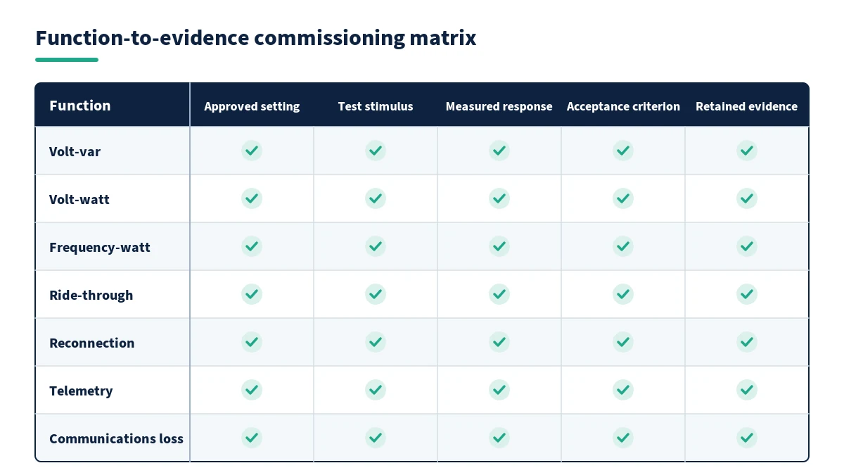
Execute the approved test procedure at the specified reference point. Confirm measurement accuracy before judging control response. Where safe and authorised, apply controlled changes or simulated commands and record the requested value, measured response, response time, limiting condition and final state.
- Verify normal start-up, synchronisation and shutdown.
- Confirm active and reactive power measurements and sign conventions.
- Test enabled voltage and reactive-power modes across representative points.
- Test enabled frequency and active-power response.
- Verify ride-through or trip behaviour using the approved method and suitable equipment.
- Confirm reconnection logic and ramp behaviour.
- Test local and remote commands, including rejected or unauthorised commands.
- Capture events, oscillography, alarms and controller records with synchronised time.
Laboratory type tests, production tests, commissioning tests and periodic tests have different scopes. Do not reproduce a hazardous laboratory disturbance on site simply because it appears in a conformance standard. The commissioning plan should allocate each requirement to the safest valid evidence source.
Acceptance should be evidence-based
For every test, record the initial condition, injected or commanded input, expected result, tolerance, actual result, instrument identification and final restoration. Marking “pass” without the supporting trace prevents later investigation when settings or firmware change.
7. Verify monitoring, alarms and fail-safe behaviour
Confirm that operators can see the values needed to understand inverter state: connection status, active and reactive power, voltage, frequency, active control mode, limits, alarms and communication quality. Compare selected telemetry with a trusted local measurement and verify timestamp alignment.
Then test credible failures. Loss of the communications link, loss of a plant controller, invalid data quality, auxiliary-supply interruption and a stale command should lead to the documented safe state. Verify alarm routing and acknowledgement, not merely local indication.
8. Establish the as-left baseline and handover
Create a final, controlled snapshot of the commissioned state. It should include firmware versions, exported settings, enabled modes, communication maps, protection records, test data, outstanding limitations, approved deviations, as-built drawings and responsible contacts. Record the exact date and configuration on which acceptance was based.
Assign ownership for future changes. Firmware updates, inverter replacement, controller modification, revised utility settings or network-address changes can invalidate earlier evidence. Define which changes require engineering review, regression testing, utility notification or recommissioning.
Hypothetical commissioning decision example
A solar-plus-storage project has compliant inverter certificates, but the site test shows reactive-power telemetry with the opposite sign at the utility interface. Local inverter behaviour appears correct; the plant controller interprets export as import and applies the wrong supervisory correction.
The correct response is not to approve the inverter because its local test passed. The team traces the point mapping, corrects the sign convention under change control, repeats the command-and-response tests, verifies alarms and archives both the failed and passed evidence. This example shows why end-to-end interface commissioning is distinct from equipment certification.
Smart inverter commissioning completion checklist
- Every test traces to an approved project requirement.
- Installed model, ratings, firmware and certificates match the approved schedule.
- Pre-energisation inspections and safety releases are complete.
- Grid-support settings have been read back and independently compared.
- Commands, telemetry, scaling, signs and timestamps are correct end to end.
- Functional tests use approved stimuli, tolerances and reference points.
- Communication-loss and fallback behaviour have been demonstrated.
- Raw traces, settings files, logs and instrument records are retained.
- The as-left baseline and future change-control owners are documented.
Develop smart-inverter engineering capability
Engineers who need a structured understanding of inverter functions, grid requirements, settings and validation can review EPW’s five-day Smart Inverters and Grid Support Functions course. The programme is part of EPW’s wider Electrical Power and Energy Engineering training portfolio.
Conclusion
Smart inverter commissioning is complete only when the installed system’s behaviour is proven against controlled requirements and preserved as an auditable operating baseline. The strongest process separates certification from site evidence, tests the whole control path and treats settings and firmware as managed engineering assets.
Ready to strengthen inverter commissioning and grid-integration decisions? Explore EPW’s Smart Inverters and Grid Support Functions course, review available dates and locations, or request course details or tailored in-house training.
Sources and References
- Institute of Electrical and Electronics Engineers. IEEE Std 1547-2018: Standard for Interconnection and Interoperability of Distributed Energy Resources with Associated Electric Power Systems Interfaces. Published 2018. Source.
- Institute of Electrical and Electronics Engineers. IEEE Std 1547.1-2020: Standard Conformance Test Procedures for Equipment Interconnecting Distributed Energy Resources with Electric Power Systems and Associated Interfaces. Published 21 May 2020. Source.
- IEEE Standards Coordinating Committee 21. IEEE Std 1547.1-2020 summary. Accessed 12 September 2026. Source.
- National Renewable Energy Laboratory. Highlights of IEEE Standard 1547-2018. 2020. Source.
- National Renewable Energy Laboratory and Electric Power Research Institute. Advanced Inverters: Capabilities, Experiences and Integration Considerations. 2019. Source.
- EPW Training. Smart Inverters and Grid Support Functions Course. Accessed 12 September 2026. Source.