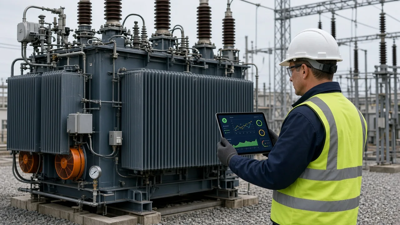

SVC vs STATCOM is a comparison between two technologies that regulate voltage by exchanging reactive power with an alternating-current network. A static var compensator (SVC) switches reactors and capacitors through thyristors; a static synchronous compensator (STATCOM) uses a self-commutated voltage-source converter. STATCOM normally retains stronger current support during depressed voltage and needs less space, while SVC can remain an economical, mature choice for large compensation duties in suitable networks.
The correct choice cannot be made from nameplate megavolt-ampere reactive (MVAr) rating alone. Transmission planners, utility engineers and industrial power-system specialists must compare the complete operating envelope, short-circuit strength, disturbance performance, harmonic design, site constraints, availability strategy and lifecycle cost.
Key takeaways
- SVC is a variable shunt susceptance; its available reactive output is strongly influenced by bus voltage.
- STATCOM behaves primarily as a controlled current source within its limits, so it generally preserves more dynamic support at low voltage.
- STATCOM usually offers a compact footprint and lower filtering demand, but project economics depend on rating, duty cycle, losses, redundancy and civil works.
- An SVC may be preferable where the grid is relatively strong, land is available and high steady-state MVAr duty dominates.
- Selection must follow validated load-flow, short-circuit, dynamic, harmonic, electromagnetic-transient and protection studies.
How SVC and STATCOM operating principles differ
SVC: controlled reactors and capacitors
A conventional SVC combines shunt capacitive and inductive branches. Typical building blocks include thyristor-controlled reactors, thyristor-switched capacitors, harmonic filters, a coupling transformer, controls, protection and cooling. The controller changes the effective shunt susceptance so the installation supplies or absorbs reactive power and regulates the connected-bus voltage.
GE Vernova’s official SVC description identifies these principal components and describes SVC applications in voltage control, transfer capability and steady-state and dynamic stability. The branch-based design is well established, scalable and can deliver substantial reactive ratings. It also occupies outdoor space and may require extensive filtering because thyristor-controlled branches generate characteristic harmonics.
STATCOM: a controlled converter voltage
A STATCOM uses a voltage-source converter (VSC), normally connected through a reactor and transformer. By controlling the converter voltage magnitude and phase relative to the AC bus, it exchanges reactive current with the network. Modern utility STATCOMs commonly use modular multilevel converter (MMC) arrangements.
The scope of IEC 62927:2017+AMD1:2023 confirms that STATCOM valves are self-commutated VSC valves and specifies electrical type and production tests for them. Siemens Energy’s STATCOM technology overview contrasts this architecture with thyristor-controlled SVC reactors and capacitors and notes the reduced harmonic-filtering requirement of its MMC design.
SVC vs STATCOM comparison table
| Selection criterion | SVC | STATCOM | Engineering implication |
|---|---|---|---|
| Core technology | Thyristor-controlled or switched reactors and capacitors | Self-commutated VSC, commonly MMC | Different models, valve tests, harmonics and maintenance skills are required |
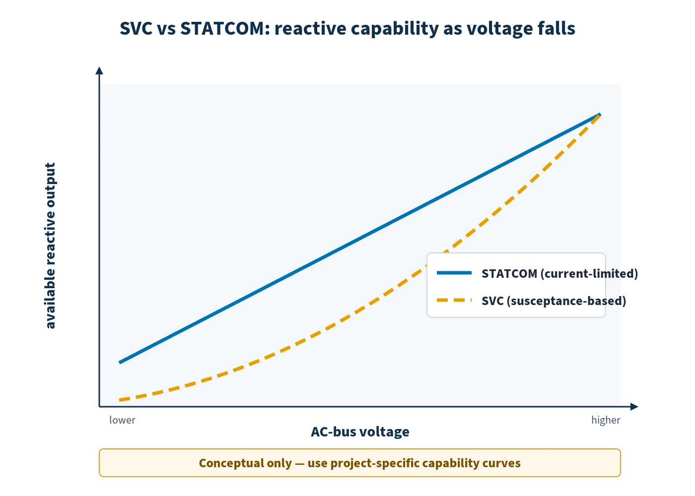
| Reactive characteristic | Variable susceptance; MVAr capability falls sharply as voltage declines | Current-limited over much of its operating range; MVAr output reduces broadly with voltage | STATCOM generally offers stronger support during deep voltage depression |
| Dynamic response | Fast, but branch switching, control and network conditions shape response | Fast continuous converter-current control | Compare guaranteed step response and recovery at the specified connection point |
| Harmonics | Controlled-reactor harmonics often require sizeable filters | MMC waveform can reduce filtering demand, although studies remain necessary | Filter duties, resonance and reactive contribution must be included in the design |
| Footprint | Often larger because of reactors, capacitors and filters | Normally more compact | Land, building, noise clearance and cable routing may alter the economic result |
| Overload and rating | Configuration-specific; passive branches can supply large steady MVAr | Semiconductor current and thermal limits are decisive | Specify continuous, short-time and contingency capability separately |
| Losses and cost | Potentially attractive for high steady-state ratings; filter and land costs matter | Converter losses and valve cost matter; compact civil design may offset them | Use a project-specific net-present-cost comparison, not a generic price rule |
| Typical fit | Large compensation duty in a sufficiently strong grid with available space | Weak-grid support, low-voltage recovery, constrained sites and rapidly changing duty | Final selection depends on the complete system study and specification |
Why low-voltage performance often drives the decision
For an SVC operating as a controlled susceptance, reactive output is approximately proportional to the square of terminal voltage for a given susceptance. If voltage falls, the shunt capacitor and reactor contribution falls rapidly. A STATCOM is constrained primarily by converter current over a substantial part of its operating envelope, so reactive power reduces more nearly in proportion to voltage until other control or equipment limits intervene.
This distinction matters during faults, post-fault recovery and weak-grid events—the moments when dynamic reactive support may be most valuable. NERC’s technical standards record on dynamic reactive resources specifically notes that SVC and STATCOM reactive capability differs under off-nominal voltage conditions and that both require capability verification. The planning model must therefore reproduce the actual control mode, current limit, voltage-dependent capability, protection and recovery logic rather than use a fixed MVAr source.
STATCOM is not automatically superior in every disturbance. Transformer impedance, available current, negative-sequence strategy, overvoltage absorption, DC-voltage control, converter blocking and post-fault control all influence its contribution. Procurement specifications should define measurable performance at the point of connection across the required voltage range.
Response, harmonics, footprint and lifecycle trade-offs
Response and control coordination
Both technologies can regulate voltage quickly, and both can support supplementary functions such as power-oscillation damping when the study and control design justify them. A STATCOM’s converter control normally gives fine, rapid current regulation. An SVC can also be highly effective, particularly where the required bandwidth and disturbance envelope align with its branch configuration.
Control speed alone is an incomplete metric. Excessively aggressive voltage regulation can interact with nearby inverter-based resources, high-voltage direct-current (HVDC) converters, excitation systems or other FACTS devices. Planners should compare droop, deadband, measurement filtering, current priority, gain scheduling and limit recovery under weak-grid and credible outage conditions.
Harmonics and resonance
SVC thyristor-controlled reactors create harmonic currents, while capacitor and filter banks change the network’s impedance profile. STATCOM MMC waveforms typically reduce low-order filtering needs, but switching harmonics, transformer effects, background distortion and control interactions still require assessment. Neither technology should be approved from a generic harmonic statement.
The harmonic study should include credible network configurations, component tolerances, filter outages and nearby converter installations. It should also distinguish compliance at the point of connection from internal equipment stress.
Land, maintainability and availability
STATCOM’s compact arrangement can be decisive at brownfield substations, urban sites or offshore platforms. SVC yards may need more land for air-core reactors, capacitor banks and filters, although layouts and voltage levels vary. Buildings, cooling, fire strategy, spares, lifting access and planned outage arrangements can reverse an apparently simple footprint or cost advantage.
CIGRE’s international SVC/STATCOM performance survey demonstrates why availability should be evaluated using consistent definitions and actual fleet evidence. Tender evaluation should examine forced-outage unavailability, scheduled maintenance, redundancy philosophy, repair time, obsolescence plans and supplier support—not availability percentage alone.
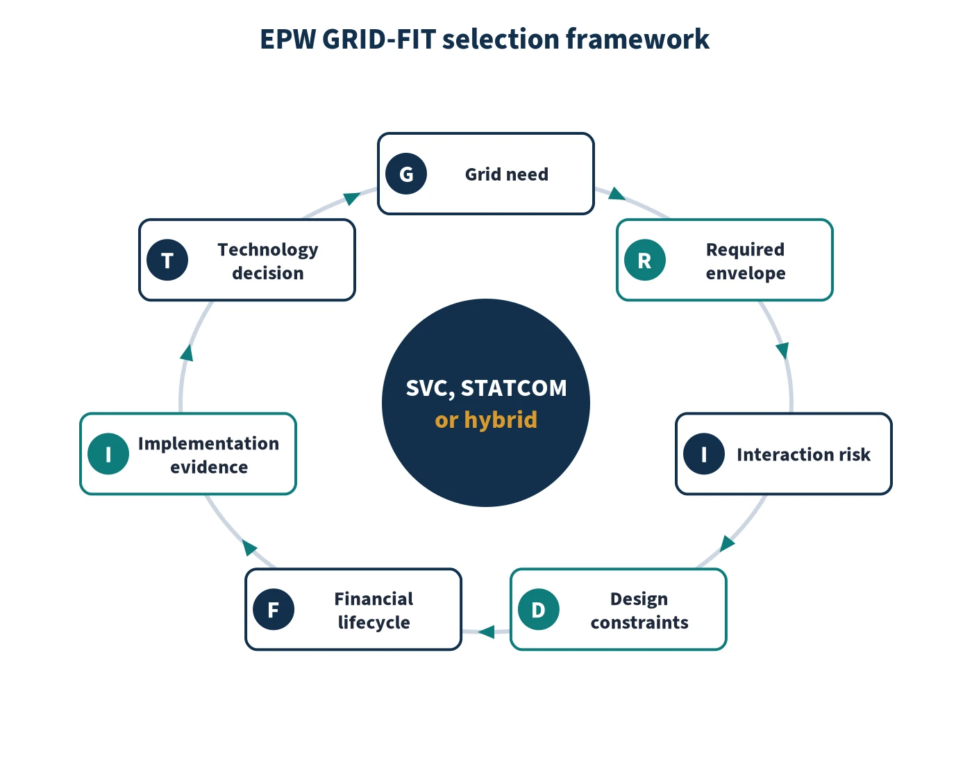
EPW GRID-FIT selection framework
- G — Grid need: define the binding problem: steady-state voltage, transient recovery, flicker, oscillation damping, transfer limit, renewable connection or contingency compliance.
- R — Required envelope: specify inductive and capacitive MVAr, bus-voltage range, response, overload duration, duty cycle and recovery after blocking or protection action.
- I — Interaction risk: screen short-circuit strength, resonances, nearby converters, control interactions, unbalance, subsynchronous phenomena and protection coordination.
- D — Design constraints: compare land, noise, building, transformer, cooling, connection voltage, transport, construction sequence and outage access.
- F — Financial lifecycle: evaluate capital expenditure, losses by operating state, auxiliaries, spares, maintenance, filter replacement, land and expected unavailability over a common study life.
- I — Implementation evidence: require validated RMS and electromagnetic-transient models, factory and site acceptance tests, model-to-test reconciliation and documented settings.
- T — Technology decision: score compliant alternatives, record sensitivities and preserve a hybrid option where switched shunts plus a smaller STATCOM meet the envelope more economically.
When should engineers choose SVC, STATCOM or a hybrid?
Consider SVC when a large, predictable shunt-compensation range is required, the connection is sufficiently strong, low-voltage current retention is not the dominant requirement, space is available and the total evaluated cost is favourable. It can be a robust solution for transmission voltage control and demanding industrial loads.
Consider STATCOM when the specification prioritises rapid current control, performance through depressed voltage, a compact footprint, weak-grid operation or coordination with variable inverter-based generation. GE Vernova’s STATCOM technical overview highlights the improved operating-voltage range and low-voltage reactive-current performance expected from VSC-based compensation.
Consider a hybrid arrangement when switched capacitors or reactors can provide economical bulk MVAr while a STATCOM covers the fast continuously controlled portion. The hybrid must still be studied as one coordinated control and protection system; combining devices does not remove resonance, switching or limit-management risks.
Studies and acceptance evidence required before selection
- Load-flow and contingency analysis across seasonal generation and demand patterns.
- Short-circuit and short-circuit-ratio assessment at the connection point.
- RMS dynamic studies for voltage recovery, oscillations, control limits and credible outages.
- Electromagnetic-transient studies for control interaction, fault recovery, switching, harmonics and resonance.
- Frequency scans and harmonic studies using measured or justified background distortion.
- Protection, insulation-coordination, equipment-duty and temporary-overvoltage studies.
- Loss evaluation over the expected duty profile, including auxiliaries and filters.
- Factory acceptance, controller hardware-in-the-loop testing where warranted, site tests and model validation.
The study programme should use manufacturer-grade models under controlled confidentiality arrangements where necessary. Model versions, parameters, limiters and protection functions must match the delivered plant. A generic positive-sequence model may be adequate for early screening but not for every interaction or commissioning decision.
Develop practical FACTS engineering capability
Engineers who need to apply these decisions can explore EPW’s Flexible AC Transmission Systems FACTS Devices course. It covers SVC, STATCOM, series and combined controllers, modelling, voltage regulation, stability, harmonics, protection and project integration. Related learning is available through EPW’s Grid Stability and Dynamic Performance Analysis course and the wider Electrical Power and Energy Engineering course category.
The defensible answer to SVC vs STATCOM is conditional: choose the technology that satisfies the required voltage-dependent operating envelope, interaction limits, site constraints and lifecycle value with evidence. Ready to strengthen your FACTS selection and modelling decisions? Review course dates and locations or request tailored in-house training through the exact EPW course page.
Sources and references
- International Electrotechnical Commission. IEC 62927:2017+AMD1:2023 — VSC valves for STATCOM: electrical testing. Consolidated version, 2023.
- North American Electric Reliability Corporation. MOD-025 and PRC-019 Consideration of Comments. 25 April 2023.
- CIGRE. Static var compensator/STATCOM performance survey results — 2017 and 2019. ELECTRA No. 323, August 2022.
- Siemens Energy. SVC PLUS (STATCOM). Product and technical overview, accessed 8 September 2026.
- GE Vernova. Static Var Compensator Solutions. Technical overview, accessed 8 September 2026.
- GE Vernova. Static Synchronous Compensator. Technical overview, accessed 8 September 2026.