An equivalent-circuit and thermal-network model gives electrical machine designers a fast, traceable way to connect current, torque and losses with winding, core and housing temperatures. The electrical model calculates the loss sources; the thermal model predicts where that heat goes. Iterating between them reveals whether a design can meet its duty without exceeding electrical, magnetic or thermal limits.
What the coupled framework does
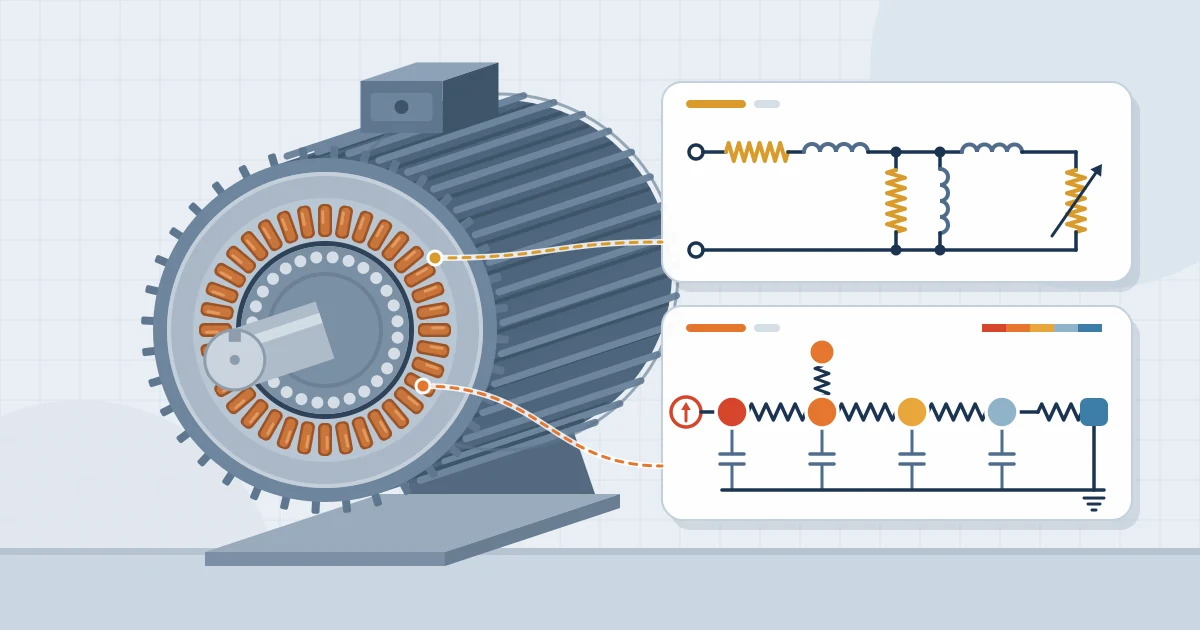
An equivalent circuit represents electromagnetic behaviour with resistances, reactances and controlled sources. A lumped-parameter thermal network represents heat paths with thermal resistances and capacitances. The framework is deliberately reduced-order: it cannot reproduce every local field or flow feature, but it can evaluate many design variants quickly and explain why a result changed.
This makes the method valuable during concept design, optimisation and design review. Detailed finite-element analysis or computational fluid dynamics can then be reserved for geometries, hot spots and cooling regimes that the reduced model cannot resolve confidently.
| Model layer | Typical inputs | Main outputs | Design decisions supported |
|---|---|---|---|
| Electrical equivalent circuit | Supply, frequency, speed or slip, resistance, leakage and magnetising parameters | Current, power factor, torque, flux indicators and separated losses | Conductor size, magnetic loading, operating point and efficiency |
| Thermal network | Losses, material properties, geometry, contact interfaces, coolant and ambient conditions | Node temperatures, heat flows and thermal time constants | Insulation system, cooling path, duty rating and temperature margin |
| Coupling loop | Temperature-dependent electrical data and operating duty | Converged performance and temperature | Feasibility, sensitivity and the next modelling fidelity |
1. Define the design inputs and acceptance criteria
Start with the duty rather than the circuit. Record terminal voltage, frequency, torque-speed envelope, starting and overload requirements, duty cycle, ambient range, altitude, enclosure, permitted cooling method and the allowable temperature rise for each critical component. IEC 60034-1:2026 provides the common rating and performance framework for rotating machines, so its definitions should be aligned with the project specification.
Separate fixed constraints from variables. Frame size, shaft height or supply may be fixed, while stack length, turns, conductor area, air-gap, slot dimensions and fan duty may be design variables. Define acceptance tests at the same time: efficiency at specified points, current, power factor, torque margin, temperature rise and transient duration.
A useful rule is that every output must answer a decision. If a predicted temperature does not connect to an insulation, cooling or duty decision, the model is probably more detailed than the current design stage requires.
2. Build the equivalent-circuit model
For a three-phase induction machine, the familiar per-phase circuit contains stator resistance and leakage reactance, a magnetising branch, and a rotor branch referred to the stator. The rotor term varies with slip, allowing the model to estimate current, input power, air-gap power, torque and rotor copper loss across the operating range. Synchronous and permanent-magnet machines use different circuit forms, but the same principle applies: represent the dominant electromagnetic relationships with parameters that can be calculated or identified.
Keep the loss ledger explicit. At minimum, separate stator copper loss, rotor or field copper loss, iron loss, mechanical loss and additional load loss. IEC 60034-2-1:2024 defines standard test methods for determining efficiency and specific losses. Its loss categories make a sound basis for mapping test evidence back to model parameters.
Copper resistance must be referenced to temperature. A first-order correction is R(T) = Rref[1 + α(T − Tref)], using the appropriate temperature coefficient and reference temperature for the conductor. Frequency, saturation, skin effect and inverter harmonics may require additional corrections. Do not hide these effects in one unexplained “stray loss” factor when they materially influence a design decision.
3. Build the lumped thermal network
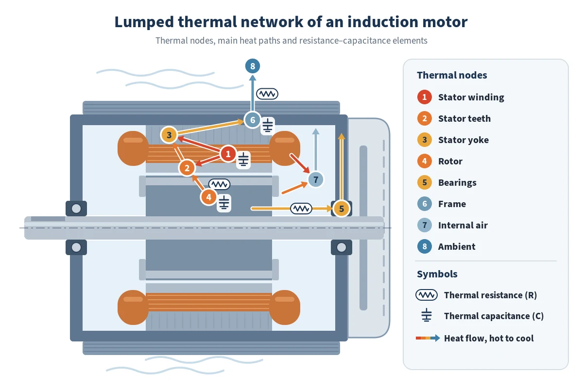
Choose nodes that correspond to components with distinct heat generation or temperature limits. A practical induction-motor network may include stator winding, stator teeth, stator yoke, rotor, shaft, end winding, frame, internal air and coolant. Connect nodes with conduction, convection or radiation paths, then connect exposed nodes to ambient or a defined coolant temperature.
Thermal resistance represents the opposition to heat flow. For a simple steady path, temperature rise is ΔT = PlossRth. Thermal capacitance represents stored heat, so a transient node follows an energy balance such as CidTi/dt = Pi − Σ[(Ti − Tj)/Rij]. The network therefore predicts both final temperatures and the time taken to approach them.
Cooling assumptions must match the declared cooling arrangement. IEC 60034-6 classifies machine cooling methods using IC codes. Use the relevant arrangement to decide which surfaces and fluids belong in the model, rather than applying a generic housing-to-air coefficient to every design.
Contact interfaces often dominate uncertainty. Slot liner, impregnation, air gaps, frame contact and end-region airflow can shift winding temperature significantly. Document each resistance source and tag it as calculated, supplier-provided, measured or assumed.
4. Couple electrical losses and temperatures
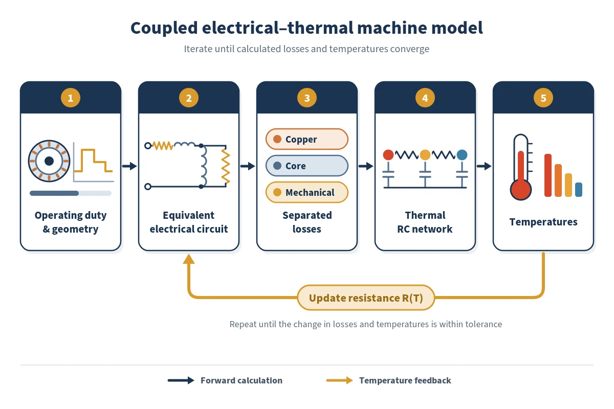
Run the electrical model at the initial reference temperature and pass the separated losses to their physical thermal nodes. Solve the thermal network for the required steady or transient duty. Then update temperature-dependent resistances, recalculate current and losses, and repeat until the change in the selected outputs falls below a defined convergence tolerance.
The loop matters because rising winding temperature increases conductor resistance. That changes copper loss and can change current, torque and efficiency. A one-way calculation may be adequate for an early comparison, but a final rating decision should use the coupled result when temperature feedback is material.
- Initialise electrical parameters and component temperatures.
- Solve the operating point and create a loss vector.
- Map each loss to the correct thermal node.
- Solve temperatures over the specified duty.
- Update electrical and, where relevant, thermal properties.
- Repeat to convergence, then test sensitivities and limits.
5. Calibrate, validate and control uncertainty
Calibration adjusts uncertain parameters using one data set; validation tests the resulting model against separate operating conditions. Typical evidence includes DC resistance, no-load and locked-rotor tests, efficiency tests, thermocouples, resistance-based winding temperature and coolant measurements. Preserve this separation so that a good fit is not mistaken for predictive capability.
Validate more than one headline number. A credible model should reproduce current, power factor, torque or speed, total loss, loss distribution and critical temperatures across several operating points. The expected efficiency class can be checked against IEC 60034-30-1:2025 where that standard applies, but class compliance does not replace design-specific thermal validation.
Use sensitivity analysis to identify what deserves better evidence. Vary slot-to-core contact resistance, end-winding convection, iron-loss coefficient, mechanical loss and ambient conditions within justified ranges. Report the temperature or efficiency range, not only a single deterministic value, when uncertain inputs influence acceptance.
Worked design example: a continuous-duty induction motor
Consider a four-pole industrial induction motor required to deliver rated torque continuously in a high ambient temperature. The initial equivalent circuit meets torque and current requirements, but the first thermal run predicts the winding as the limiting node. The model therefore directs attention to the winding-to-core path and external cooling rather than to rotor geometry.
The designer evaluates three controlled changes: increasing conductor area, improving slot impregnation and increasing frame airflow. The electrical model shows how conductor area changes resistance and slot allocation; the thermal model shows how impregnation and airflow alter heat paths. Each variant is re-run through the coupled loop, then compared against efficiency, starting performance, manufacturability and temperature margin.
This is not a claim that one change is universally best. It demonstrates the value of the framework: it makes trade-offs explicit and prevents a thermal improvement from being accepted without checking its electrical and manufacturing consequences.
When to use this model—and when to escalate
| Design question | Recommended approach | Reason |
|---|---|---|
| Compare turns, conductor size, loading and cooling concepts | Coupled equivalent circuit and lumped thermal network | Fast, interpretable and suitable for many variants |
| Resolve local saturation, torque ripple or complex leakage paths | Electromagnetic finite-element analysis linked to the network | Field distribution controls the answer |
| Resolve end-region or duct airflow and local heat-transfer coefficients | Computational fluid dynamics or targeted testing | Flow geometry is too detailed for assumed lumped coefficients |
| Approve a final rating or compliance claim | Validated model plus applicable standard tests | Prediction must be supported by traceable evidence |
Escalate modelling fidelity when the result is highly sensitive to a poorly known parameter, when safety margin is small, or when a local phenomenon controls performance. Reduced-order and high-fidelity models should complement each other, with test results closing the loop.
Electrical machine design model checklist
- Define the duty, environment, constraints and pass/fail criteria.
- Use a circuit topology appropriate to the machine type and supply.
- Separate losses and map each loss to a physical thermal node.
- Declare the cooling method and every boundary condition.
- Correct temperature-dependent parameters within an iterative loop.
- Record the source and uncertainty of each influential parameter.
- Calibrate with one evidence set and validate with another.
- Check several electrical and thermal outputs across the duty range.
- Escalate to field or flow simulation only where the decision requires it.
- Retain model version, assumptions and test data for design review.
Develop practical machine-design capability
Engineers who need to connect electromagnetic design, loss calculation, thermal behaviour and performance validation can build these skills in EPW’s Electrical Machines Design and Performance course. Explore the wider Electrical Power and Energy Engineering training portfolio to place machine design within broader power-system practice.
References
- International Electrotechnical Commission, IEC 60034-1:2026, Rotating electrical machines – Rating and performance.
- International Electrotechnical Commission, IEC 60034-2-1:2024, Standard methods for determining losses and efficiency from tests.
- International Electrotechnical Commission, IEC 60034-6:1991, Methods of cooling (IC Code).
- International Electrotechnical Commission, IEC 60034-30-1:2025, Efficiency classes of line operated AC motors.