
To build and validate an EMT simulation model, define the study question first, set a justified network boundary, implement frequency-dependent and control behaviour at the required fidelity, initialise the case, and validate it in layers. A credible model must reproduce component responses and system events within declared acceptance criteria, remain numerically stable, and document where it is not valid.
This nine-step workflow applies to utility and industrial power networks, including studies involving inverter-based resources, HVDC, weak grids, switching and fast control interactions. It is software-neutral: the engineering evidence matters more than the platform name.
When an EMT model is appropriate
Electromagnetic transient simulation solves instantaneous electrical quantities in the time domain, so it can represent fast switching, unbalanced faults, converter controls, protection logic and waveform distortion. RMS or positive-sequence tools remain more efficient for many electromechanical stability questions. Use EMT when the study outcome depends on sub-cycle behaviour, detailed power-electronic controls, network resonance, switching transients or interactions that a phasor-domain model cannot represent adequately.
CIGRE’s system-strength guidance notes that wide-area EMT modelling is increasingly needed where phasor-domain models may not predict controller interactions and instabilities reliably. The modeller should still justify every detailed area. Expanding the network without a study reason increases data requirements, run time and opportunities for error.
1. Define scope and acceptance criteria
Write a one-page model specification before drawing the network. State:
- the study questions and decisions the results will support;
- faults, switching actions, operating points and contingencies to be tested;
- required outputs, measurement locations and simulation duration;
- frequency range and fastest control or switching phenomena of interest;
- network boundary, external equivalents and equipment exclusions;
- data confidentiality and black-box model constraints; and
- quantitative or qualitative acceptance criteria.
Acceptance criteria should name the reference data and the permitted difference in steady-state values, peak response, settling time, oscillation frequency and protection operation. Do not invent a universal tolerance. Use limits agreed with the asset owner, manufacturer, network operator or applicable connection process. A model can be stable and still be inaccurate.
2. Collect and grade model data
Create a model data register. For each parameter, capture the value, unit, source document, revision, equipment applicability, owner, date and confidence grade. Prefer as-built settings and type-tested or factory-tested response data over generic templates.
| Data group | Minimum content | Validation evidence |
|---|---|---|
| Network | Topology, voltage bases, source strength, X/R ratio and grounding | Power-flow case, fault study and single-line diagram |
| Lines and cables | Geometry or sequence data, length, frequency dependence and terminations | Design records and impedance checks |
| Transformers | Vector group, ratio, leakage, saturation, grounding and tap position | Test report and nameplate data |
| Converters | Power stage, inner controls, plant controller, limits, protections and delays | Manufacturer model and test comparisons |
| Conventional machines | Electrical parameters, excitation, governor and protection | Approved dynamic data and disturbance records |
| Switchgear and protection | Breaker timing, arrester curve, relay logic and reclosing | Settings files and commissioning evidence |
If confidential control code is supplied as a compiled model, record the software and compiler dependencies, version, expiry behaviour, available parameters and test interface. The Southwest Power Pool EMT Model Requirements show why model usability, protection representation, controller detail and supplier checklists are treated as formal deliverables for inverter-based resources.
3. Set the network boundary and equivalents
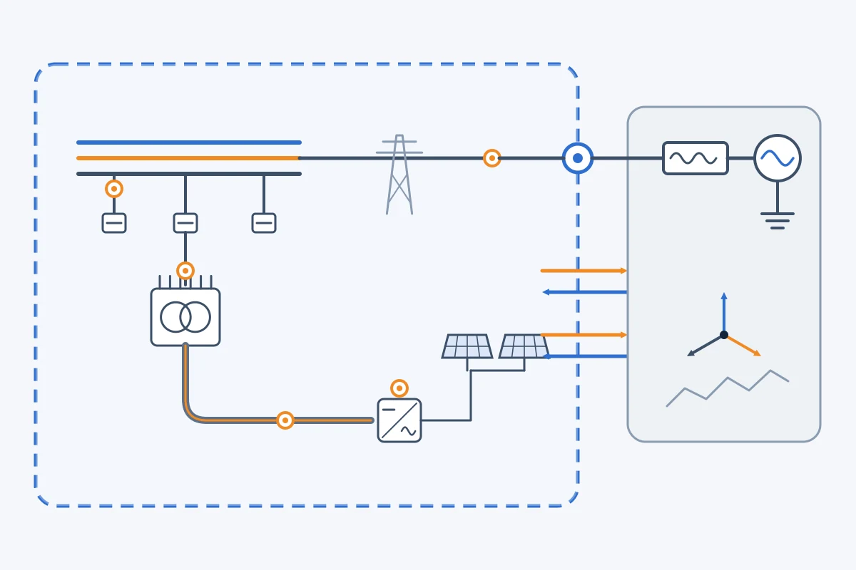
Include the part of the network whose electromagnetic behaviour can influence the result. Use detailed three-phase models around the disturbance, converters, resonant circuits and electrically close plants. Represent the remote system with an equivalent that preserves relevant short-circuit strength, X/R ratio, phase angle, frequency and sequence behaviour.
Validate the equivalent against the source power-flow and fault-study cases. Match pre-disturbance voltage, active and reactive power, three-phase fault level and, where unbalance matters, negative- and zero-sequence quantities. A fixed Thévenin source may be sufficient for a local switching study but inadequate for a multi-infeed control-interaction study.
4. Implement components and controls at the required fidelity
Select component models from the phenomenon of interest. Frequency-dependent line and cable models are normally appropriate for fast transients and resonances; simpler equivalents may be justified for slower control studies. Represent transformer connections and grounding explicitly. Add saturation, hysteresis or arrester non-linearity only when they can affect the result.
For inverter-based resources, include fast current control, phase-locked loop or grid-forming logic, current limits, control-mode changes, plant-level controls, measurement filters, communication delays and protection that operates in the simulated time window. Do not substitute a generic controller when the study concerns proprietary control behaviour.
Use consistent base values and signs. Keep each equipment group in a reusable module with parameters separated from control logic. Label measurement channels and units. A model that only its author can operate is not a durable engineering asset.
5. Initialise the model correctly
Reproduce the target operating point before applying disturbances. Check bus voltages, active and reactive power, transformer taps, machine loading, converter setpoints and controller internal states. Allow the case to settle without a test event and plot key signals.
Investigate any drift, oscillation, limiter activity or unexpected protection during the settling period. Common causes include inconsistent power-flow and EMT data, incorrect phase sequence, poor control initialisation, hidden deadbands, unbalanced source impedances or an unsuitable external equivalent. Do not mask an unstable initial condition by starting the event earlier.
6. Validate individual components
Use staged tests before connecting the complete network. For each controlled device, test steady-state setpoint tracking, small reference steps, voltage and frequency ramps, balanced and unbalanced faults, recovery, current limiting and protection thresholds. Test passive components using impedance, energisation or switching responses appropriate to the study.
Compare the response with factory tests, hardware tests, commissioning records or an accepted benchmark model. Overlay traces on the same time axis and quantify the features that matter. Visual similarity alone is weak evidence. A validation report should record test conditions, model version, reference version, results, discrepancies and disposition.
SPP explicitly requires additional validation evidence where an inverter model is not based on real control code and calls for testing across different system strengths. That principle is broadly useful: validation should challenge the operating regions in which the model will be used, not only a strong-grid nominal case.
7. Validate network-level events
After component tests pass, run system events in increasing complexity:
- steady-state cross-check against power flow and fault level;
- single switching operations and simple faults;
- fault clearing, reclosing and protection sequences;
- weak-grid and contingency operating points;
- multiple converter or HVDC interactions; and
- recorded-event replay where suitable disturbance data exist.
For event replay, align timestamps, pre-event operating point, breaker sequence and measurement filtering. Distinguish errors caused by uncertain event data from errors caused by the model. Document channels that cannot be compared. Field records are valuable, but they are not automatically perfect ground truth.
8. Check numerical robustness and sensitivity
Repeat representative cases with a smaller time step. A materially different result indicates that the original step may be too large or that switching and control events are poorly resolved. Check interpolation, network solution options, sampling rates and discontinuity handling. The required time step depends on the fastest represented dynamics and model implementation; do not treat one value as universal.
Then vary uncertain physical parameters such as source strength, X/R ratio, controller delay, cable data and operating point. A conclusion that disappears under a small credible change is not robust. Separate numerical sensitivity from physical sensitivity and retain both in the study record.
9. Approve, package and control the model
Release the model with an approved input register, validation report, user guide, software dependencies, known limitations and example cases. Assign a unique version and checksum. Freeze the study version, then manage later changes through a controlled register that states why each change was made and which validation tests were repeated.
Define expiry or review triggers: firmware change, controller setting change, network reinforcement, plant modification, new disturbance evidence or software migration. CIGRE’s technical publication library provides a continuing source of expert power-system practice, but local network-operator requirements and project agreements remain controlling for acceptance.

Illustrative weak-grid example
Suppose a grid-following inverter plant connects to a 220 kV bus where a transmission outage can reduce system strength. The study question is whether fault recovery and post-fault oscillations remain acceptable. The detailed area includes the plant controller, aggregated inverter blocks, collector network, main transformer, nearby lines and the contingency. The remote network is reduced to an equivalent matched to the relevant operating cases.
The modeller first validates the plant block against manufacturer tests, then matches the intact and outage operating points. Fault tests cover location, duration, residual voltage and clearing sequence. The study repeats critical cases across credible source strength, X/R ratio and controller-delay ranges. The conclusion reports where the model is validated and identifies any conditions for which a vendor update or hardware comparison is still required. This is an illustrative workflow, not a claim about a real project.
Common EMT modelling mistakes
- Building the network before defining the decision and acceptance criteria.
- Using a wide-area model with unverified data simply because more detail appears better.
- Mixing equipment revisions or control settings without a traceable register.
- Validating only steady state or only a nominal strong-grid condition.
- Using generic converter controls for a control-interaction decision.
- Ignoring protection, limits, delays and mode changes.
- Changing the time step without checking whether results change.
- Presenting plots without quantitative comparisons or model limitations.
- Reusing a model after firmware or network changes without revalidation.
Final EMT model checklist
- The study scope, boundary and phenomena are explicit.
- Every material input has a source, revision and confidence grade.
- Steady-state power flow and fault levels are matched.
- Components pass staged tests before system events are run.
- Control limits, protection and delays are represented where relevant.
- Results are insensitive to a justified reduction in time step.
- Uncertain physical parameters are sensitivity-tested.
- Validation criteria, discrepancies and limitations are documented.
- The released model has controlled versioning and review triggers.
Build practical EMT analysis capability
Engineers who want structured practice with transient-network representation, model setup and interpretation can develop these skills through EPW’s Electromagnetic Transient Analysis Using EMT Software course. Browse the wider Electrical Power and Energy Engineering category for related power-system training.
References
- CIGRE, System Strength.
- Southwest Power Pool, Electromagnetic Transient Model Requirements for Inverter-Based Resource Interconnection, Revision 1, 2023.
- CIGRE, eCIGRE Technical Publications on Electric Power Systems.
- North American Electric Reliability Corporation, Reliability Standards.
- Electric Reliability Council of Texas, PSCAD Templates and DMVIEW, 2024.