

AI-generated illustration created to represent the article’s subject. It does not depict an actual EPW course, trainer, participant, client, event or venue.
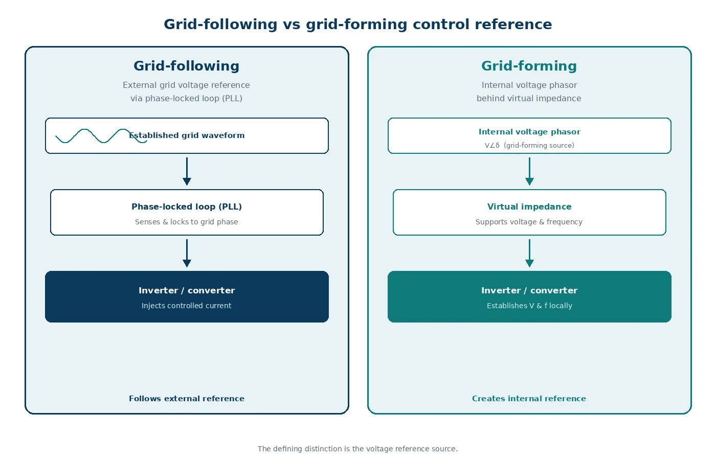
Grid-following inverters regulate current or power by synchronising to an existing grid voltage waveform, whereas grid-forming inverters establish and regulate their own internal voltage phasor. The practical difference is most visible in weak systems and disturbances: grid-following control needs a sufficiently strong reference, while grid-forming control can help establish voltage, frequency and system strength.
This distinction matters to power-system planners, protection engineers, renewable developers and commissioning teams. It affects stability studies, plant controls, fault behaviour, energy headroom, model validation and connection requirements. Neither mode is automatically superior in every project; the correct choice depends on the service required and the surrounding network.
Key takeaways
- Grid-following control normally uses a phase-locked loop or equivalent synchronisation method to track an external voltage angle.
- Grid-forming control maintains an internal voltage phasor and responds immediately to changes in the external system.
- Grid-forming capability can improve performance in low-system-strength areas, but it does not remove the need for current limits, protection studies or stored-energy headroom.
- Procurement specifications should describe measurable functions and test conditions rather than relying on the label “grid-forming”.
- Electromagnetic transient models and staged field tests are usually needed when converter controls interact quickly with a weak network.
Grid-following vs grid-forming inverters: direct comparison
| Criterion | Grid-following inverter | Grid-forming inverter |
|---|---|---|
| Primary reference | Tracks an external grid voltage angle and frequency | Maintains an internal voltage phasor |
| Typical controlled quantity | Injected current, active power and reactive power | Terminal voltage and frequency relationship, with power emerging through control laws |
| Synchronisation | Commonly uses a phase-locked loop | Does not depend on a conventional phase-locked loop for its primary fast response |
| Weak-grid behaviour | May become difficult to tune as system strength falls | Can support stable operation and nearby grid-following resources when correctly designed |
| Frequency response | Usually follows measured frequency through supplementary control | Can respond through droop, virtual-synchronous-machine or related control |
| Voltage support | Provides reactive current within control and current limits | Regulates a voltage source behind an impedance, subject to current limits |
| Islanded operation | Normally needs another source to establish voltage and frequency | May establish an island when the plant, energy source and controls are designed for it |
| Fault response | Controlled and limited current; behaviour depends on sequence controls and protection settings | Also current-limited; may provide a faster or differently shaped response, but not synchronous-machine fault current by default |
| Study emphasis | Synchronisation stability, control interaction and fault ride-through | Voltage-source behaviour, current limiting, transitions, energy limits and multi-device coordination |
| Typical application | Strong-grid solar, wind and battery plants where another source establishes the reference | Weak-grid battery systems, microgrids, restoration duties and networks needing additional stability capability |
The North American Electric Reliability Corporation (NERC) notes that terminology has not always been universal. Its recommended functional definition centres on maintaining an internal voltage phasor that is constant or nearly constant over the sub-transient-to-transient timeframe, enabling an immediate response to external-system changes [1]. This functional definition is more useful than assuming that one branded algorithm proves grid-forming performance.
How the two control philosophies behave
Grid-following control
A grid-following converter measures the terminal voltage, estimates its phase and controls current relative to that reference. Outer loops convert active-power, reactive-power or direct-current-voltage objectives into current commands. Inner loops then regulate converter current rapidly.
This architecture is effective when the grid voltage is a dependable reference. In a weak network, however, the inverter’s own injected current can materially change the voltage that its synchronisation loop is trying to follow. Poorly coordinated bandwidths, delay, filters and plant-level controls can then cause oscillation or loss of stable operation.
Grid-forming control
A grid-forming converter creates an internal voltage magnitude and angle using a control law such as droop control, virtual synchronous machine control or virtual oscillator control. Active and reactive power change as the internal voltage interacts with the network impedance. Current-limiting logic still intervenes to protect semiconductor devices during severe disturbances.
NREL’s roadmap for moving from grid-following to grid-forming distributed inverter controllers describes the transition as a system-level control challenge, not simply a firmware switch [2]. Device controls, feeder characteristics, communications, protection and restoration objectives must be considered together.
What both modes share
Both use power-electronic switching, filters, measurement systems and layered controls. Both have thermal, voltage, current and energy constraints. Either can provide active-power control, reactive support and fault ride-through when specified and validated. The distinction is therefore about the control reference and dynamic behaviour, not the presence of an inverter enclosure.
System services, benefits and limitations
System strength and stable operation
Grid-forming control can improve voltage and frequency stability in areas with high inverter-based resource penetration or low short-circuit strength. NERC’s 2023 functional specification recommends evaluating performance before wide-scale implementation and provides tests for transitions, load changes, low short-circuit ratio and oscillation damping [3].
This benefit is not unlimited. A grid-forming inverter reaches a semiconductor current limit much sooner than a synchronous generator reaches its electromagnetic limit. The current-limiting strategy can change the apparent voltage-source behaviour exactly when the network is most disturbed. Engineers must test the implemented control, not an ideal voltage source.
Frequency and voltage support
Grid-forming controls can respond to frequency or angle changes without waiting for a separate frequency measurement loop. Droop settings determine how multiple resources share active and reactive power. The available response nevertheless depends on the energy source: a battery at its state-of-charge limit or a curtailed renewable plant without headroom cannot sustain an active-power increase.
Protection and fault current
Neither control mode should be assumed to reproduce the magnitude, waveform or sequence content of synchronous-machine fault current. AEMO’s grid-forming inverter work specifically examines whether fault contribution has sufficient magnitude, duration and composition for protection relays to operate correctly [4]. Protection settings, negative-sequence response, current priority and recovery behaviour require explicit assessment.
Black start and islanding
Grid-forming control is a prerequisite for many inverter-based black-start or islanded systems, but it is not a complete restoration solution. Auxiliary supplies, energisation current, transformer flux, communications, load pickup, protection zones and energy duration must also be designed. A plant may be grid-forming while connected yet lack the equipment or procedures for a dead-network start.
A practical selection framework
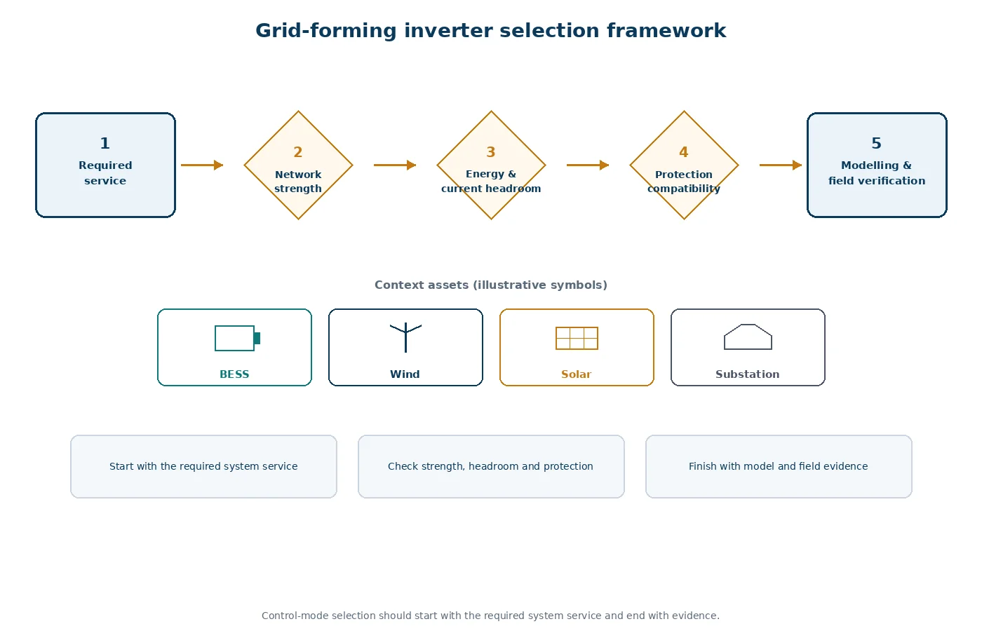
Use four questions to decide what the project needs:
- What must the plant do? Define ordinary dispatch, voltage support, weak-grid operation, islanding, black start and restoration as separate services.
- What network conditions must it withstand? Specify short-circuit strength, credible outages, impedance range, nearby converter interactions and minimum synchronous generation.
- What physical headroom exists? Check inverter current margin, battery state of charge, renewable curtailment, direct-current source dynamics and thermal duration.
- How will performance be demonstrated? Link every required function to model data, acceptance criteria, factory tests, site tests and post-event monitoring.
| Project condition | Likely control direction | Engineering caution |
|---|---|---|
| Strong grid; conventional sources provide reference and strength | Grid-following may meet the connection need efficiently | Still test control interactions and fault ride-through |
| Weak connection point with many inverter-based resources | Assess grid-forming capability or a coordinated mix | Validate current limiting and multi-inverter tuning |
| Battery required to energise an island | Grid-forming with black-start functions | Confirm auxiliary supply, transformer energisation and sustained energy |
| Solar plant without storage or curtailment headroom | Either control may support voltage, but sustained frequency support is constrained | Do not specify active-power response the energy source cannot deliver |
| Protection depends on high fault current | Control label alone is insufficient | Study relay sensitivity, sequences and alternative protection principles |
A worked planning example
Consider a battery energy storage system proposed at a remote renewable-energy hub. Present short-circuit strength is acceptable, but the retirement of a nearby synchronous unit will reduce the available voltage reference. Several grid-following wind and solar plants already share the connection area.
The planner should not ask only whether the new battery is “grid-forming”. The requirement should describe stable operation across the forecast impedance range, active- and reactive-power response, transition following the synchronous-unit trip, current-limited fault behaviour, oscillation damping and support to nearby resources. The study programme would compare a grid-following base case, a grid-forming case and credible control-setting variations.
The procurement decision can then be based on verified system outcomes. A mixed fleet may be appropriate: enough grid-forming capacity to establish robust voltage and frequency behaviour, with other converters remaining grid-following where this meets their duty.
Modelling, specification and commissioning
- Define operating envelopes. Include active-power level, state of charge, voltage, frequency, network impedance and equipment availability.
- Use fit-for-purpose models. Root-mean-square studies support broad planning; electromagnetic transient studies are needed for fast control interactions, current limiting and detailed faults.
- Request validated parameters. Identify software version, plant-controller settings, protection logic and model limitations.
- Test transitions. Examine faults, islanding, reconnection, changes in system strength, mode changes and recovery from current limit.
- Coordinate multiple devices. Review droop, virtual impedance, measurement filters and plant-level controls across vendors.
- Stage commissioning. Progress from factory tests and hardware-in-the-loop evidence to controlled site tests and monitored service demonstration.
AEMO’s engineering-roadmap publications collect current work on inverter fault contribution, performance and integration, illustrating why evidence must remain connected to the specific power system and connection process [5].
Common specification mistakes
- Using “grid-forming” as a binary purchasing label without functional acceptance tests.
- Assuming synthetic inertia is identical to physical synchronous inertia.
- Ignoring state-of-charge, curtailment and current headroom.
- Validating only a strong-grid operating point.
- Using an ideal voltage-source model that omits current limiting and protection.
- Assuming greater fault current without checking magnitude, duration and sequence content.
- Changing converter settings without rechecking coordination across the plant and network.
Build practical smart-inverter capability
The correct control choice connects network needs, converter behaviour, studies and evidence. EPW’s Smart Inverters and Grid Support Functions course develops practical understanding of smart-inverter controls, grid-support functions, modelling, interconnection and validation. You can also explore the wider Electrical Power and Energy Engineering training portfolio.
Conclusion
Grid-following inverters are effective when a strong external voltage reference is available. Grid-forming inverters can help establish voltage and frequency behaviour in weaker, converter-dominated or islanded systems. The engineering decision should be based on required services, network conditions, physical headroom, protection compatibility and verified dynamic performance—not terminology alone.
Sources and references
- NERC, Grid Forming Technology, 2021.
- National Renewable Energy Laboratory, Stabilizing the Power System in 2035 and Beyond, 2021.
- NERC, Grid Forming Functional Specifications for BPS-Connected Battery Energy Storage Systems, 2023.
- AEMO, Grid-Forming Inverter Protection-Quality Fault Current Trial.
- AEMO, Engineering Roadmap Execution Reports.